Installing both exhaust turbochargers
Further information is available.
Risk of burning!
- Perform all work only on components that have cooled down.
Heavy components can lead to injury or damage.
- Remove and install heavy components with the aid of another person/other persons.
Contaminant or foreign body.
Contamination can result in malfunctions, loss of function or leaks.
- Adhere to the utmost cleanliness.
- Protect components from contamination e.g. by covering.
- Close off line connections with seal plugs.
The sealing surfaces must be free of oil, grease and cleaning agents.
Prepare for the installation of the exhaust turbocharger
- Check the oil feed and oil return lines for contamination or obstruction and clean or replace as needed.
- If the oil feed and/or oil return lines are heavily contaminated, we recommend changing the motor oil and the oil filter.
- If installed: Check the coolant feed and coolant return lines for the exhaust turbocharger for contamination or obstruction and clean or replace as needed.
- Check the screw connections and plug connections of all lines for accuracy.
- Check air filter for contamination and clean or replace as needed.
- Check correct functioning of crankcase ventilation.
- Replace all gaskets.
Parts: Seals
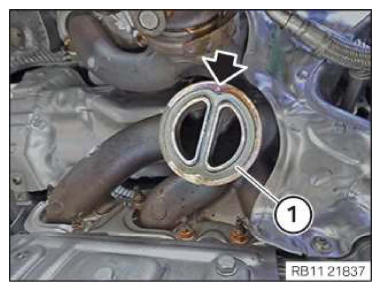
- Replace the seal (1).
Parts: Gasket
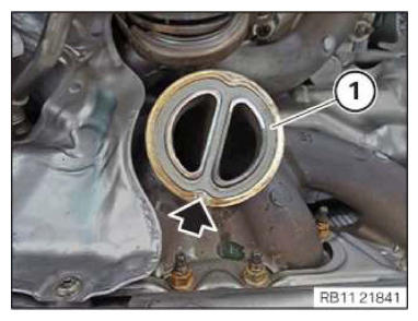
- Check the pin (arrow) for damage and replace the exhaust manifold if necessary.
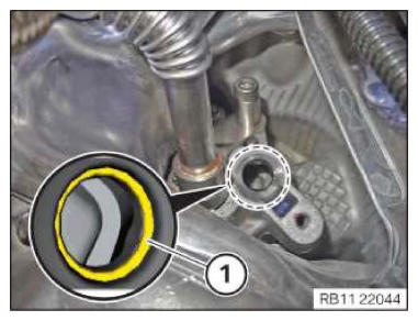
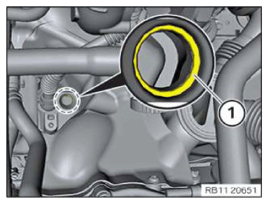
- Make sure that the O-ring (1) does not fall into the oil duct in the engine block.
- Replace O-ring (1).
Parts: O-ring
If the O-ring (1) cannot be disassembled, the oil return lid must be disassembled.
- Coat O-ring (1) with engine oil.
Engine oil
Technically suitable engine oils for BMW Group engines
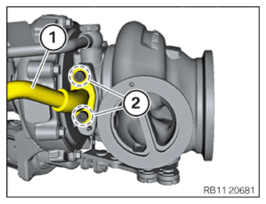
- Loosen screws (2).
- Remove the oil return line (1).
- Ensure that the sealing surfaces in the area of the oil return line are planar and free from oil and grease.
- Replace oil return line (3) after each disassembly of the exhaust turbocharger.
Parts: Oil return line
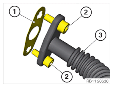
- Replace the seal (1).
Parts: Gasket
- Replace screws (2).
Parts: Screws
- Position screws (2) in oil return line (3).
- Position the seal (1) on the screws (2).
- Position the oil return line (1).
- Screws (2) must
be tightened with the aid of an support person.TIGHTENING TORQUES SPECIFICATION
Oil return line at the exhaust turbocharger M6x16
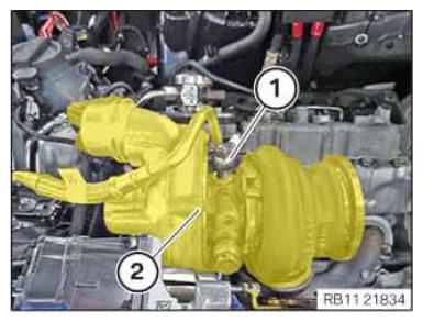
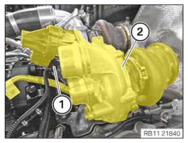
Replace screws.Joining torque 5 Nm Angle of rotation 60° - Feed in and install the exhaust turbocharger (2) at right with the coolant lines and oil return line.
- During installation of the right exhaust turbocharger (2), make sure that the oil return line is correctly positioned in the oil return cover.
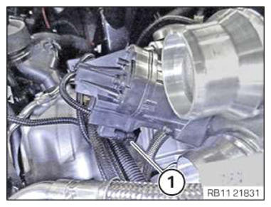
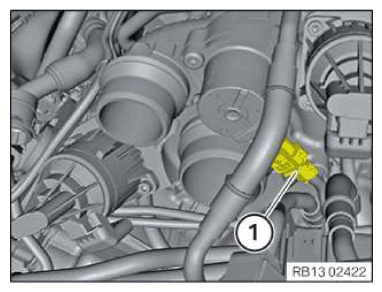
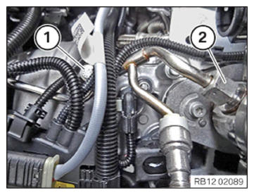
- Make sure the oil feed line (1) is positioned correctly.
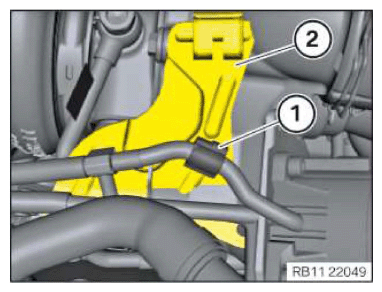
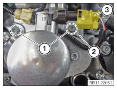
- Fasten the wiring harness mounting (1) to the holder (2).
- Insert the holder (2).
- Tighten down screws (1).TIGHTENING TORQUES SPECIFICATION
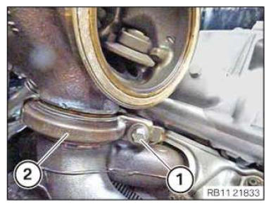
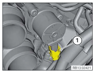
Holder of sensor system M6x16 screw tightening torque 8 Nm - Replace the V-clip (2).
Parts: V-band clamp
- Position V-clip (2).
- Tighten down screw (1).TIGHTENING TORQUES SPECIFICATION
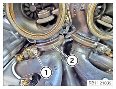
Exhaust turbocharger to exhaust manifold V-band clamp Replace V-band clamp. tightening torque 20 Nm - Tighten the screw (1) on the oil return pipe (2).TIGHTENING TORQUES SPECIFICATION
Oil return line to oil return cover M6 tightening torque 10 Nm - Connect connectors (1) and lock.
The connector (1) must engage audibly.
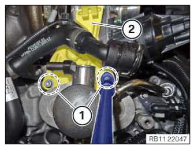
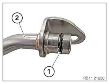
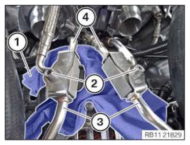
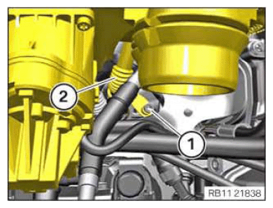
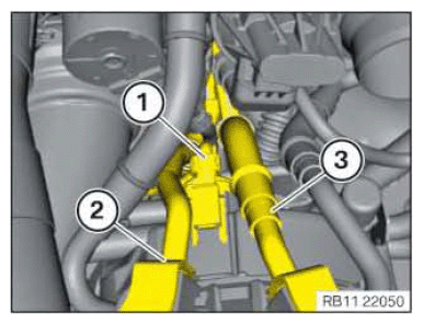
- Replace sealing ring (1) of the coolant line (2).
Parts: Sealing ring
- Connect coolant lines (4).
- Connect coolant lines (3).
- Tighten down screws (2).TIGHTENING TORQUES SPECIFICATION
Coolant line from exhaust turbocharger to bracket M6x30 tightening torque 8 Nm - Remove the lint-free rag (1).
- Connect connectors (1) and lock.
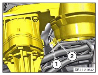
- Replace the screw (1).
Parts: Screw
- Replace the sealing ring or sealing rings (2).
Parts: Sealing ring or sealing rings
- Make sure that when installing sealing rings without a fitting aid (bridge), both sealing rings are replaced.
- Position screw (1) with the sealing ring or sealing rings (2) on the oil feed line.
- Position oil feed line.
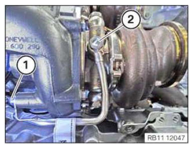
- Screw in the banjo bolt (2) several threads.
- Hand-tighten the bolt (1).
- Tighten the banjo bolt (2).TIGHTENING TORQUES SPECIFICATION
Banjo bolt for oil feed line to exhaust turbocharger M10x1
Replace the screw and sealing rings.Joining torque 8 Nm Angle of rotation 70° - Tighten down screw (1).TIGHTENING TORQUES SPECIFICATION
Oil feed line to exhaust turbocharger M6x16 tightening torque 10 Nm - Replace the seal (1).
Parts: Gasket
- Check the pin (arrow) for damage and replace the exhaust manifold if necessary.
- Make sure that the O-ring (1) does not fall into the oil duct in the engine block.
- Replace O-ring (1).
Parts: O-ring
If the O-ring (1) cannot be disassembled, the oil return lid must be disassembled.
- Coat O-ring (1) with engine oil.
Engine oil
Technically suitable engine oils for BMW Group engines
- Loosen screws (2).
- Remove the oil return line (1).
- Ensure that the sealing surfaces in the area of the oil return line are planar and free from oil and grease.
- Replace oil return line (3) after each disassembly of the exhaust turbocharger.
Parts: Oil return line
- Replace the seal (1).
Parts: Gasket
- Replace screws (2).
Parts: Screws
- Position screws (2) in oil return line (3).
- Position the seal (1) on the screws (2).
- Position the oil return line (1).
- Screws (2) must
be tightened with the aid of an support person.TIGHTENING TORQUES SPECIFICATION
Oil return line at the exhaust turbocharger M6x16
Replace screws.Joining torque 5 Nm Angle of rotation 60° - Feed in and install the exhaust turbocharger (2) at left with the coolant lines and oil return line.
- When installing the right exhaust turbocharger (2), make sure that the oil return line is correctly positioned in the oil return cover.
- Connect connectors (1) and lock.
The connector (1) must engage audibly.
- Replace the V-clip (2).
Parts: V-band clamp
- Position V-clip (2).
- Tighten down screw (1).TIGHTENING TORQUES SPECIFICATION
Exhaust turbocharger to exhaust manifold V-band clamp Replace V-band clamp. tightening torque 20 Nm - Tighten the screw (1) on the oil return pipe (2).TIGHTENING TORQUES SPECIFICATION
Oil return line to oil return cover M6 tightening torque 10 Nm - Feed the coolant return line (2) above the coolant feed line (3).
- Connect connectors (1) and lock.
- Replace sealing ring (1) of the coolant line (2).
Parts: Sealing ring
- Connect coolant lines (4).
- Connect coolant lines (3).
- Tighten down screws (2).TIGHTENING TORQUES SPECIFICATION
Coolant line from exhaust turbocharger to bracket M6x30 tightening torque 8 Nm - Remove the lint-free rag (1).
- Replace the screw (1).
Parts: Screw
- Replace the sealing ring or sealing rings (2).
Parts: Sealing ring or sealing rings
- Make sure that when installing sealing rings without a fitting aid (bridge), both sealing rings are replaced.
- Position screw (1) with the sealing ring or sealing rings (2) on the oil feed line.
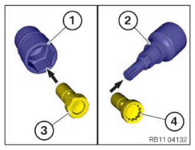
- Determining the screw type and selecting the appropriate socket wrench:
Screw type Matching socket wrench Hexagon screw (3) Commercial socket wrench (1) Multi-tooth screw (4) Multi-tooth socket wrench (2) - Position oil feed line.
- Screw in the banjo bolt (2) several threads.
- Hand-tighten the bolt (1).
- Tighten the banjo bolt (2).TIGHTENING TORQUES SPECIFICATION
Banjo bolt for oil feed line to exhaust turbocharger M10x1
Replace the screw and sealing rings.Joining torque 8 Nm Angle of rotation 70° - Tighten down screw (1).TIGHTENING TORQUES SPECIFICATION
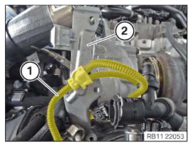
Oil feed line to exhaust turbocharger M6x16 tightening torque 10 Nm - Position the retaining plate (2).
- Secure the wiring harness (1) on the retaining plate (2).
- Position the retaining plate (2).
- Tighten down screws (2).TIGHTENING TORQUES SPECIFICATION
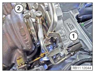
Holder control sensor cable to the cylinder head cover M6x16 tightening torque 8 Nm - Connect connectors (3) and lock.
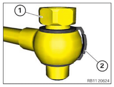
- Position union nut (2) and turn it a few times.
- Position screw (1) and turn it a few times.
- Tighten union nut (2).TIGHTENING TORQUES SPECIFICATION
Fuel delivery line to high pressure pump M14 tightening torque 30 Nm - Tighten down screw (1).TIGHTENING TORQUES SPECIFICATION
Fuel supply line to cylinder head cover/cylinder head M6x16 tightening torque 10 Nm - Connect connectors (1) and lock.
- Connect connectors (1) and lock.
Follow-up work
- Refer to INSTALLING THE CLEAN AIR PIPE OF CYLINDER BANK 2 .
- Refer to INSTALLING THE LEFT CHARGE AIR LINE .
- Refer to CLOSING THE HIGH-TEMPERATURE COOLANT CIRCUIT .
- Refer to INSTALLING THE UNDERBODY PROTECTION OF THE STEERING GEAR OR THE FRONT THRUST FIELD .
- Refer to INSTALLING THE FRONT UNDERBODY PROTECTION OR FRONT THRUST FIELD .
- Refer to INSTALLING THE FRONT LEFT BOTTOM WHEEL ARCH COVER .
- Refer to INSTALLING THE FRONT BOTTOM RIGHT WHEEL ARCH COVER .
- Refer to INSTALLING FAN COWL .
- Refer to INSTALLING THE REAR TOP CROSS CONNECTION .
- Refer to INSTALLING FRONT CROSS CONNECTION .
- Refer to INSTALLING THE RIGHT INTAKE FILTER HOUSING WITH THE RIGHT FRONT-END STRUT .
- Refer to INSTALLING LEFT INTAKE FILTER HOUSING WITH LEFT FRONT-END STRUT .
- Refer to INSTALLING THE COVER ON THE LEFT AND RIGHT IN THE ENGINE COMPARTMENT AT THE TOP .
- Refer to INSTALLING THE CATALYTIC CONVERTER FOR CYLINDERS 5 TO 8 .
- Refer to RELEASING THE HEAT SHIELD .
- Refer to INSTALLING THE CENTER COWL UPPER PART .
- Refer to INSTALLING TENSION STRUT ON SHOCK TOWER .
- Refer to INSTALLING WINDSHIELD PANEL COVER .
- Refer to INSTALLING LEFT AND RIGHT WIPER ARM .
- Refer to INSTALLING THE REAR RIGHT ENGINE COMPARTMENT COVER .
- Refer to INSTALLING THE COVER OF THE ENGINE COMPARTMENT ON THE REAR LEFT .
- Refer to INSTALLING RIGHT HEAT SHIELD .
- Refer to INSTALLING LEFT HEAT SHIELD .
- Refer to INSTALLING HEAT SHIELD, TOP .
- Refer to INSTALLING THE RIGHT OXYGEN SENSOR MONITOR .
- Refer to INSTALLING THE LEFT OXYGEN SENSOR MONITOR .
- Refer to PARTIALLY INSTALLING THE RIGHT LAMBDA OXYGEN SENSOR .
- Refer to PARTIALLY INSTALLING THE LEFT LAMBDA OXYGEN SENSOR .
- Refer to INSTALLING THE RETAINING BRIDGE .
- Refer to INSTALLING EXHAUST SYSTEM .
- Refer to INSTALLING CENTER REAR UNDERSHIELD .
- Refer to INSTALLING THE CONNECTING SUPPORTS ON THE TUNNEL .