Install injectors
NOTE:
TECHNICAL INFORMATION
When assembling, it is essential to observe screwing sequences and tightening torques.
Failure to comply with the regulations can lead to leaks and damage.
When assembling, it is essential to observe screwing sequences and tightening torques.
Failure to comply with the regulations can lead to leaks and damage.
NOTE:
The description is for one component only. The procedure is identical for all further components.
Retrofitting and, if necessary, replacing the foam jacket
NOTE:
The description is for one component only. The procedure is identical for all further components.
Check
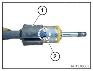
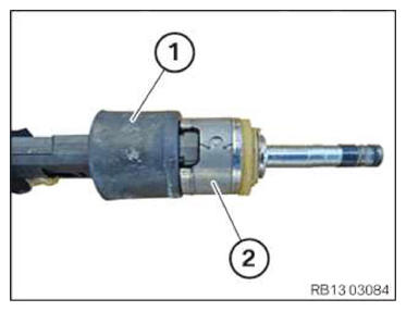
- Check if foam jacket (1) is installed on injector (2).
Result
» Foam jacket (2) is not installed.
Measure
- Retrofit foam jacket (2) as described in the following step.
Parts: Foam jacket
Result
» Foam jacket (2) is installed.
Measure
- Replace foam jacket (2) as described in the following step.
Parts: Foam jacket
- Position foam jacket (1) in the recess of the injector in area (2).
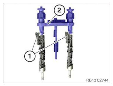
- Mount the injectors (1) on the special tool (2) 2 410 777 .
- Align the plug connections of injectors (1) in the correct installation position.
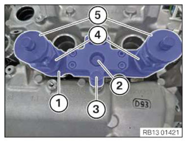
- Insert the injectors in the injector bore holes with special tool (1) 2 410 777 .
- Screw in the screws (2) and (3) on the injector shaft with a few thread starts.
- Check, if the pull-out thread (4) and the threaded sleeves (5) are correctly mounted.
- Tighten screws (2) and (3).TIGHTENING TORQUES SPECIFICATION
Special tool 2 410 777 to injector well M6 Tightening torque 8 Nm - Adjust the torque wrench (1) to 2 Nm, anti-clockwise.
- Position the torque wrench (1) and special tool (2) 0 496 106 (11 8 720) on the hexagon head of special tool 2 410 777 .
- Turn the torque wrench (1) in anti-clockwise direction until 2 Nm apply.
- Remove special tool 2 410 777
.
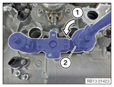
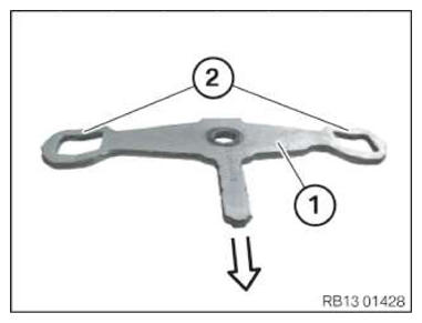
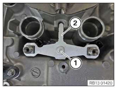
- Install hold-down device (1) with curvatures (see arrow) downwards.
- Mount the hold-down device (2) on the injectors.
- Screw in the screw (1) by a few turns only.
Follow-up work
- Refer to INSTALLING THE RIGHT HIGH-PRESSURE RAIL .
- Refer to INSTALL THE HIGH-PRESSURE RAIL ON THE LEFT .
- Refer to INSTALL ALL IGNITION COILS
- Refer to INSTALLING COOLANT EXPANSION TANK .
- Refer to INSTALLING THE CONTROL UNIT BRACKET FOR CYLINDERS 5 TO 8 .
- Refer to INSTALL CLEAN AIR PIPE, TOP .
- Refer to INSTALLING THE COVER OF THE LEFT DME CONTROL UNIT .
- Refer to INSTALLING CONTROL UNIT HOLDER FOR CYLINDERS 1 TO 4 .
- Refer to INSTALLING THE COVER OF THE RIGHT DME CONTROL UNIT .
- Refer to DISCONNECTING ALL BATTERY GROUND LEADS .