Install full-flow oil filter
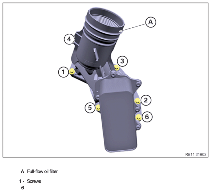
Full-flow oil filter
NOTE:
TECHNICAL INFORMATION
Only G05 and G07
On vehicles with an active stabilizer (ARS), the fan cowl must be removed to crank the engine.
For additional information see: REMOVING AND INSTALLING/REPLACING FAN COWL WITH ELECTRIC FAN .
Only G05 and G07
On vehicles with an active stabilizer (ARS), the fan cowl must be removed to crank the engine.
For additional information see: REMOVING AND INSTALLING/REPLACING FAN COWL WITH ELECTRIC FAN .
NOTE:
TECHNICAL INFORMATION
The sealing surfaces must be free of oil, grease and cleaning agents.
The sealing surfaces must be free of oil, grease and cleaning agents.
- Have a cleaning cloth ready.
NOTE:
RISK OF DAMAGE
Damage to the engine.
If the engine is manually rotated in the wrong direction of rotation, the engine can be damaged.
Damage to the engine.
If the engine is manually rotated in the wrong direction of rotation, the engine can be damaged.
- Only rotate the engine manually in the correct direction of rotation: a) clockwise when looking at the damper, or b) counterclockwise when looking at the chain drive, b) applies only if the timing chain is installed in the rear.
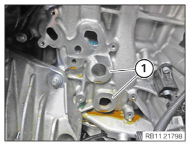
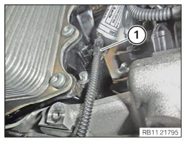
- Crank the engine with the special tool 0 493 380 (116 480) until the motor oil flows in the area of the oil duct (1).
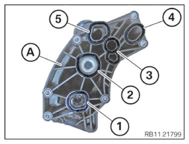
- Replace seals (1) to (5) on the full-flow oil filter (A).
Parts: Seals
NOTE: RISK OF DAMAGE
Damage to the surface.
The use of metal-cutting tools (e.g., emery cloths) for cleaning surfaces can damage them and lead to leaks and/or engine damage.- Do not use any metal-cutting tools.
- Clean the sealing residue off the sealing surface (1) on the crankcase using the special tool 0 495 102 (11 4 470).
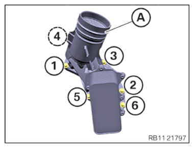
- Feed in and install the full-flow oil filter (A) from above.
- Tighten screws in the order (1) to (6).NOTE: Tighten the bolts in 360 degree steps.TIGHTENING TORQUES SPECIFICATION
Full-flow oil filter to crankcase Captive screw M6
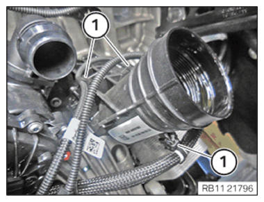
Observe tightening sequence!Joining torque 4 Nm tightening torque 10 Nm - Secure clamps (1).
- Secure clamps (1).NOTE: TECHNICAL INFORMATION
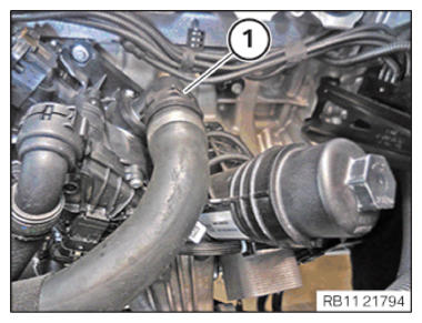
Make sure that the connections are locked correctly. The locks must engage audibly. - Connect coolant hose (1) and lock.
Follow-up work
- Refer to INSTALLING THE OIL FILTER ELEMENT .
- Refer to INSTALLING THE INTAKE PLENUM .
- Refer to INSTALLING THE TANK VENT VALVE .
- Refer to INSTALLING THE CONTROL UNIT HOLDER .
- Refer to PARTIALLY INSTALLING THE INTEGRATED POWER SUPPLY MODULE (PDM) .
- Refer to INSTALLING THE DME CONTROL UNIT .
- Refer to INSTALLING THE RESONATOR WITH THE TOP CLEAN AIR PIPE .
- Refer to INSTALLING INTAKE SILENCER HOUSING .
- Refer to INSTALLING FAN COWL .
- Refer to INSTALLING THE REAR TOP CROSS CONNECTION .
- Refer to INSTALLING FRONT CROSS CONNECTION .
- Refer to INSTALLING BOTH FRONT-END STRUTS .
- Refer to INSTALLING THE COVER ON THE LEFT AND RIGHT IN THE ENGINE COMPARTMENT AT THE TOP .
- Refer to FILLING ENGINE OIL .
- Refer to OPENING THE OIL FILLER CAP .
- Refer to CONNECTING NEGATIVE BATTERY CABLE .
- Refer to ACTIVATING THE 48 V ELECTRICAL SYSTEM .
- Refer to FILLING AND VENTING THE HIGH-TEMPERATURE COOLANT CIRCUIT .
- Refer to FILLING AND VENTING THE LOW-TEMPERATURE COOLANT CIRCUIT .
- Refer to CHECKING ENGINE OIL LEVEL .
- Refer to INSTALLING THE THRUST FIELD .
- Refer to INSTALLING THE UNDERBODY PROTECTION OF THE STEERING GEAR OR THE FRONT THRUST FIELD .
- Refer to INSTALLING THE FRONT UNDERBODY PROTECTION OR FRONT THRUST FIELD .
- Refer to INSTALLING ACOUSTIC COVER AT REAR .
- Refer to INSTALLING THE FRONT HOOD SEAL AT THE REAR .
- Refer to INSTALLING ACOUSTIC COVER .
- Refer to TAKING HOOD OUT OF THE SERVICE POSITION .