Remove counterbalance shafts
NOTE:
DANGER
High-voltage system.
The high-voltage system operates on the basis of hazardous, electrical voltage and high currents. Danger to life through electric shock!
High-voltage system.
The high-voltage system operates on the basis of hazardous, electrical voltage and high currents. Danger to life through electric shock!
- All work on the high-voltage system may only be carried out by specially trained and technically experienced personnel.
- For additional information see:
- For additional information see:
WARNING:
Hot fluids.
Risk of scalding!
Risk of scalding!
- Conduct all work in the vehicle wearing appropriate personal protective equipment only.
WARNING:
Hot surfaces.
Risk of burning!
Risk of burning!
- Perform all work only on components that have cooled down.
NOTE:
TECHNICAL INFORMATION
Collect and dispose of emerging fluids. Observe country-specific waste disposal regulations.
Collect and dispose of emerging fluids. Observe country-specific waste disposal regulations.
Preliminary work
- Refer to REMOVING THE OIL FILLER CAP .
- Refer to DRAINING THE MOTOR OIL
- Refer to REMOVING ENGINE .
- Refer to INSTALL THE ENGINE ON THE ASSEMBLY STAND
- Refer to REMOVING THE DRIVE BELT FOR COOLANT PUMP .
- Refer to REMOVE TANK VENT VALVE .
- Refer to REMOVE INTAKE PLENUM .
- Refer to REMOVE IGNITION COILS .
- Refer to REMOVE THE HIGH PRESSURE LINE BETWEEN THE HIGH PRESSURE PUMP AND THE RAIL .
- Refer to REMOVING INJECTORS .
- Refer to REMOVE FUEL DELIVERY LINE .
- Refer to REMOVE HIGH PRESSURE PUMP .
- Refer to REMOVE BOTH ACTUATORS (ENGINE REMOVED)
- Refer to REMOVING AUXILIARY COOLANT PUMP FOR THE EXHAUST TURBOCHARGER .
- Refer to REMOVE THE COOLANT RETURN LINE FOR THE EXHAUST TURBOCHARGER (AUXILIARY COOLANT PUMP REMOVED) .
- Refer to REMOVE THE COOLANT FEED LINE FOR THE EXHAUST TURBOCHARGER (COOLANT RETURN LINE REMOVED) .
- Refer to REMOVE FRONT ENGINE ENCAPSULATION .
- Refer to REMOVING THE CYLINDER HEAD COVER (ENGINE REMOVED)
- Refer to REMOVE THE ACOUSTIC COVER OF THE OIL SUMP .
- Refer to REMOVING THE THERMOSTAT FROM THE TRANSMISSION OIL LINES .
- Refer to TURNING THE ENGINE ON THE VIBRATION DAMPER
- Refer to BLOCK THE CRANKSHAFT IN HE TDC FIRING POSITION OF CYLINDER 1 .
- Refer to BLOCKING THE CAMSHAFTS
- Refer to REMOVE THE CHAIN TENSIONER (ENGINE REMOVED) .
- Refer to RELEASING THE VANOS CENTRAL VALVE .
- Refer to REMOVING INTAKE ADJUSTER .
- Refer to REMOVE EXHAUST CAMSHAFT ADJUSTER .
- Refer to DISASSEMBLING THE SPECIAL TOOL 2358 122 .
- Refer to REMOVE THE OIL RETURN LINE FOR THE EXHAUST TURBOCHARGER .
- Refer to REMOVE CYLINDER HEAD .
- Refer to REMOVING THE VIBRATION DAMPER .
- Refer to REMOVING FLYWHEEL .
- Refer to REMOVE OIL SUMP .
- Refer to REMOVE REAR TIMING CASE COVER .
- Refer to REMOVE THE OIL VACUUM PUMP (530e 2018-2020) , or REMOVE THE OIL VACUUM PUMP (530e xDrive 2018-2020) .
- Refer to REMOVING THE OIL DEFLECTOR
NOTE:
TECHNICAL INFORMATION
To facilitate disassembly and installation, rotate the engine with special tool 002300 to a more convenient working position.
To facilitate disassembly and installation, rotate the engine with special tool 002300 to a more convenient working position.
NOTE:
In the following operations, the engine is rotated by 180 degrees. The bottom points up.
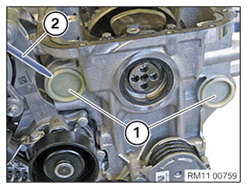
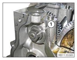
- Remove both sealing caps (1) with a suitable tool (2).
- Rotate the crankshaft to the lower dead center of the first cylinder.
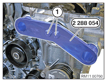
- Mount the special tool 2288 054
and abut the bolts (1).NOTE: The description is for one component only. The procedure is identical for all further components.
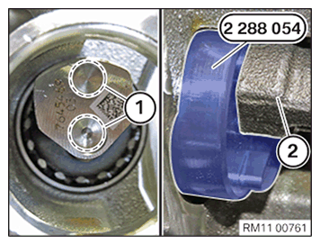
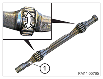
- Make sure the special tool 2288 054 is correctly fitted in the guides (1) of the counterbalance shafts (2).
- If necessary, turn the crankshaft slightly.
- Tighten special tool 2288 054. TIGHTENING TORQUES SPECIFICATION
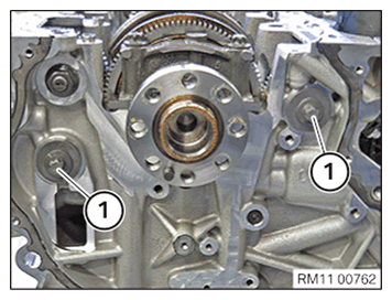
Special tool 2288 054 to crankshaft Tightening torque 20 Nm - Loosen screws (1).
- Loosen screws (1).
- Guide the special tool 2288 054
out and remove.NOTE: The description is for one component only. The procedure is identical for all further components.
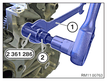
- Screw the special tool 2458 114
into the gear of the counterbalance shaft and hold it up with an open-end spanner (1).NOTE: The gears are pressed onto the counterbalance shaft with a taper and can only be released with the special tool 2458114.
- Release the counterbalance shaft by screwing in the screw (2) of the special tool 2458 114 from the gear.
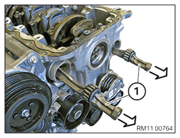
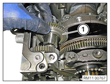
- Carefully remove the counterbalance shafts (1) from the crankcase towards the front.
Do not drop the counterbalance shafts (1) into the bearing positions because this may damage the crankcase.
- Check all needle bearings of the counterbalance shafts (1) for damage and replace as necessary.
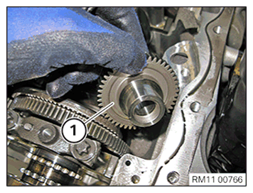
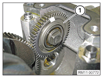
- Remove the gear (1).
- Remove the gear (1).
- Loosen nut (1).
- Remove the gear (1).