Disassemble cylinder head
Preliminary work
- Refer to INSTALLING THE CYLINDER HEAD ON THE SPECIAL TOOL .
- Refer to REMOVING THE EXHAUST TURBOCHARGER (CYLINDER HEAD REMOVED) .
- Refer to INSTALLING THE CYLINDER HEAD ON THE SPECIAL TOOL (EXHAUST TURBOCHARGER REMOVED) .
Checking the position of the intake camshaft (cylinder head removed)
Check
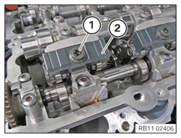
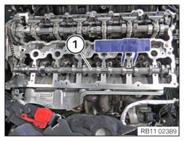
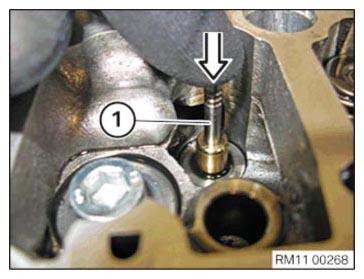
- Check position of the intake camshaft on the respective cylinders.
Result
» Cam (1) of the intake camshaft runs on the intermediate lever.
Measure
- Continue to crank the intake camshaft on the mounting flats.
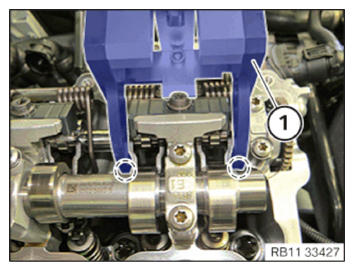
Checking the position of the intake camshaft at cylinders 3 and 4 (cylinder head removed)
Check
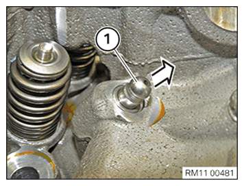
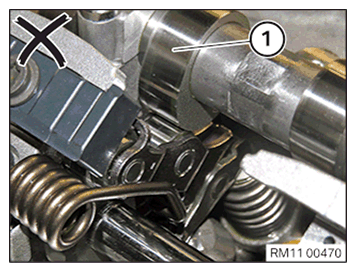
- Check the position of the intake camshaft at cylinder 3 and 4.
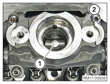
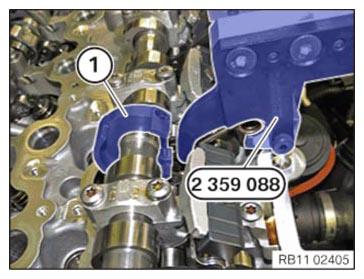
To remove the torsion springs on cylinders 3 and 4, the camshaft sensor wheel (1) of the intake camshaft must be in the position shown.
Result
» The camshaft sensor wheel (1) of the intake camshaft is not in the position shown.
Measure
- Continue to crank the intake camshaft on the mounting flats.
Remove torsion springs
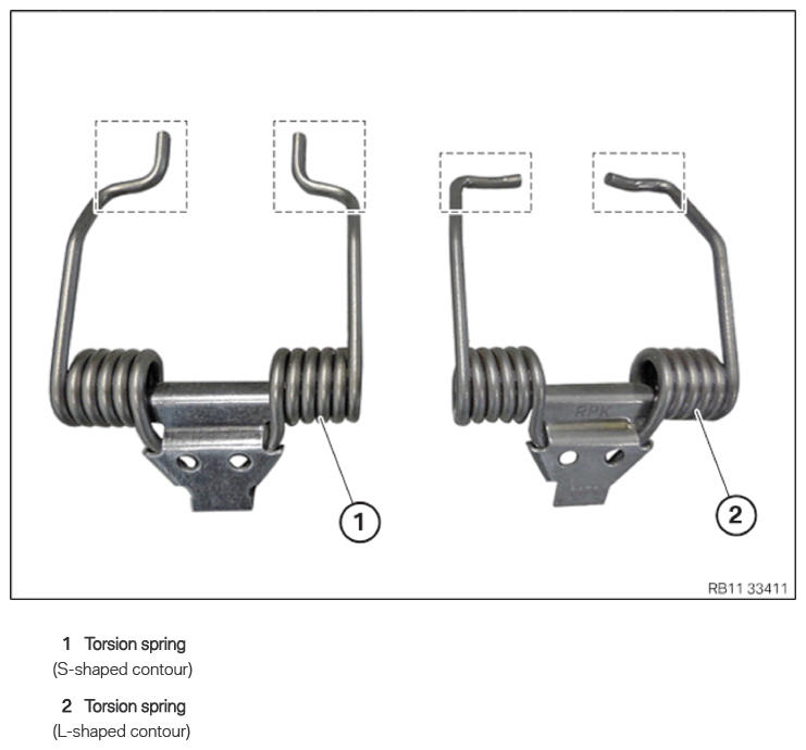
Torsion spring
Injury hazard!
- The use of the specified special tool (tool) is mandatory.
- Carry out the described steps properly.
Wear safety goggles.
For disassembly and installation of the torsion spring, special tool 2 359 088 is used. Due to technical modifications in the torsion spring, special tool 5 A0B 120 is mounted on the existing special tool 2 359 088.
Information on modification can be found in the additional information.
Alternative to the new special tool 5 A24 F30, the already known special tool SWZ: 2 359 088 can be used in modified form.
Information on modification can be found in the additional information.
The modified special tool is upward compatible.
When replacing one or more torsion springs:
When removing the torsion spring, it is imperative to note the part number of the torsion spring.
A mixed installation of torsion springs is only permitted in combination with the appropriate intermediate lever.
For further information on possible combinations, see the applicable BMW parts catalogue.
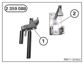
- Keep set of special tools 2 359 088
for removing the torsion spring with an S-shaped contour ready:
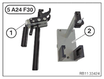
Number Description 1 Clamping lever 2 Mount for the clamping lever (for a torsion spring with an S-shaped contour) - Keep the set of special tools 5 A24 F30
or, alternatively, the modified special tool 2 359 088
ready for removing the torsion spring with an L/S-shaped contour:
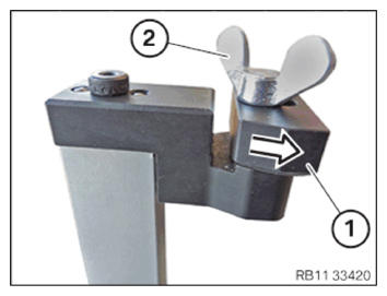
Number Description 1 Clamping lever 2 Mount for the clamping lever (for a torsion spring with an L/S-shaped contour) - Version with a torsion spring with an s-shaped contour with set of special tools 5 A24 F30 or the modified special tool 2 359 088:
Move shaped part (1) to the contact surface in the arrow direction.
Turn wing screw (2) until hand-tight.
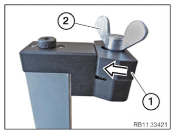
- Version with a torsion spring with an L-shaped contour with the set of special tools 5 A24 F30 or the modified special tool 2 359 088:
Move shaped part (1) to the contact surface in the arrow direction.
Turn wing screw (2) until hand-tight.
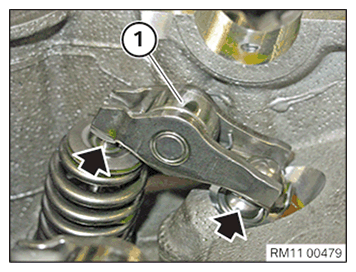
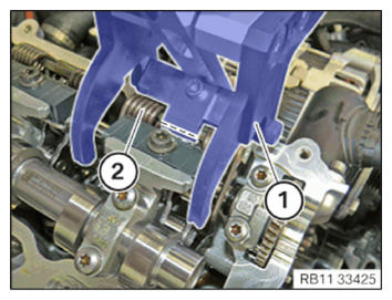
- Open clamping lever (1) and position it on torsion spring (2).
- Ensure that clamping lever (1) rests flat on the cylinder head in area (2).
- Close clamping lever (1) carefully until snap-in hooks (3) engage audibly.
Check
- Check if clamping lever (1) is positioned correctly on the torsion spring in the marked areas.
Result
» Clamping lever (1) is not positioned correctly on the torsion spring.
Measure
- Relax clamping lever (1) carefully and repeat the process.
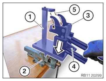
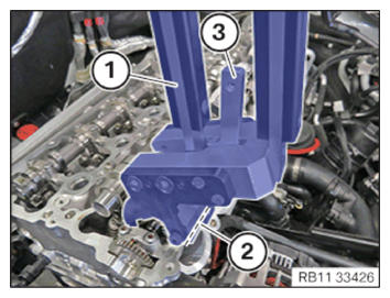
- Clamp mount (1) in vice (2).
- Position the clamping lever (3) with the preloaded torsion spring (5) in the mount (1) in the arrow direction.
Snap-in hooks (4) of clamping lever (3) are used to relax clamping lever (3).
Torsion spring (5) is thus relaxed.
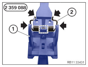
- Version with a torsion spring with an s-shaped contour and the special tool 2 359 088:
Unlock clamping lever (1) of special tool 2 359 088 carefully in the corresponding mount.
Ensure that torsion spring (2) rests correctly in the lateral guides (arrows) and mark of clamping lever (1) when releasing it.
Place torsion spring (2) properly in special tool 0 495 105 (11 4 480).
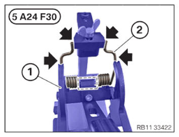
- Version with a torsion spring with an s-shaped contour and set of special tools 5 A24 F30 or the modified special tool 2 359 088:
Unlock the clamping lever (1) of the set of special tools 5 A24 F30 or alternatively the modified special tool 2 359 088 in the corresponding mount carefully.
Ensure that torsion spring (2) rests correctly in the lateral guides (arrows) and mark of clamping lever (1) while releasing it.
Place torsion spring (2) properly in special tool 0 495 105 (11 4 480).
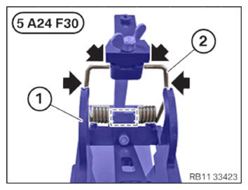
- Version with a torsion spring with an L-shaped contour and set of special tools 5 A24 F30 or the modified special tool 2 359 088:
Unlock the clamping lever (1) of the set of special tools 5 A24 F30 or the modified special tool 2 359 088 in the corresponding mount carefully.
Ensure that torsion spring (2) rests correctly in the lateral guides (arrows) and mark of clamping lever (1) while releasing it.
Place torsion spring (2) properly in special tool 0 495 105 (11 4 480).
- Repeat the steps for the remaining torsion springs.
Removing all gates
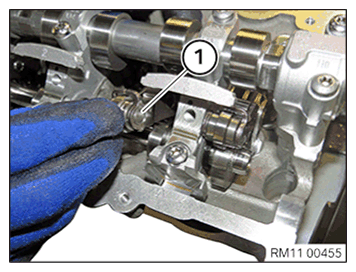
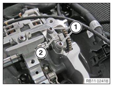
- Loosen screw (1).
- Remove the gate (2) and place it arranged in order into the special tool 0 495 105 (11 4 480).
- Repeat the step for all gates.
Removing all intermediate levers
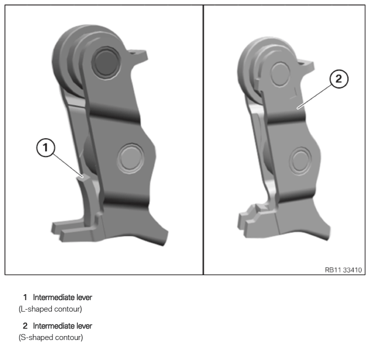
Intermediate lever
NOTE: TECHNICAL INFORMATION
When replacing one or more intermediate levers:
When removing the intermediate lever, it is imperative to note the part number of the intermediate lever.
A mixed installation of intermediate levers is only permitted in combination with the appropriate torsion spring.
For further information on possible combinations, see the applicable BMW parts catalogue. - Remove the intermediate lever (1) and arrange it in the special tool 0 495 105 (11 4 480) in order.
- Repeat the step for all intermediate levers (1).
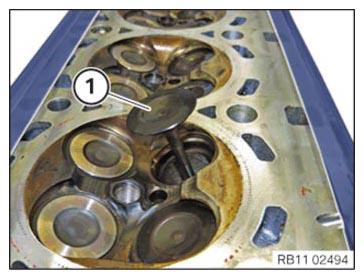
Remove intake camshaft
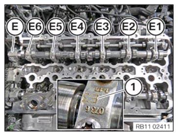
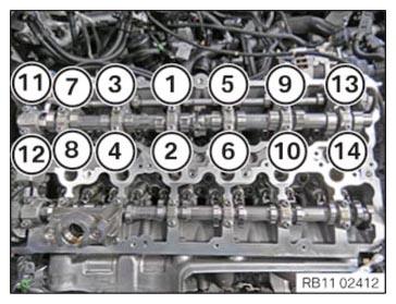
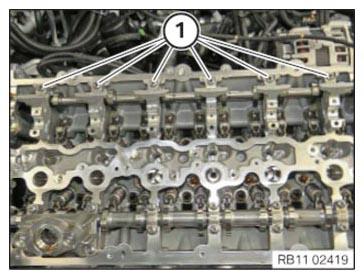
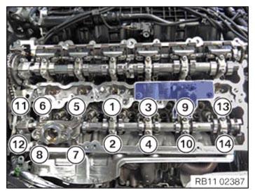
- Observe numbering of intake camshaft bearing caps from (E1) to (E6).
Intake camshaft bearing cap (E) is a thrust bearing.
- Loosen screws in the order (14) to (1).
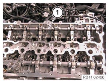
- Set all intake camshaft bearing caps neatly in the special tool 0 495 105 (11 4 480).
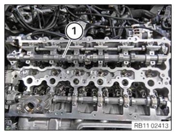
- Remove intake camshaft (1) in upward direction.
Removing the servomotor for the eccentric shaft
WARNING: Hot surfaces.
Risk of burning!- Perform all work only on components that have cooled down.
NOTE: RISK OF DAMAGE
Contaminant or foreign body.
Contamination can result in malfunctions, loss of function or leaks.- Adhere to the utmost cleanliness.
- Protect components from contamination e.g. by covering.
- Close off line connections with seal plugs.
NOTE: TECHNICAL INFORMATION
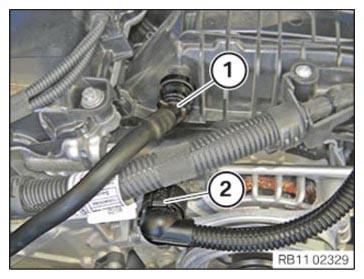
Collect and dispose of emerging fluids. Observe country-specific waste disposal regulations. - Unlock ventilation line (1) and detach from intake plenum.
- Unlock connector (2) and detach.
- Motor oil may leak when detaching the servomotor, keep cleaning cloth ready.
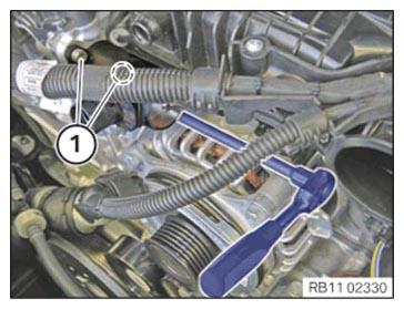
- Loosen screws (1).
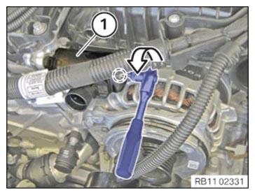
- Turn servomotor (1) on the screw in marked area towards the left in order to release the eccentric shaft.
- Detach the servomotor (1) from the cylinder head simultaneously.
- Turn wave maximum up to the end stop towards the left.
Remove eccentric shaft
- Release screws (1) and set down the bearing cap neatly in special tool 0 495 105 (11 4 480).
- Release screws (1) and set down the bearing bracket neatly in special tool 0 495 105 (11 4 480).
- Remove the eccentric shaft (1) from the top.
Remove exhaust camshaft
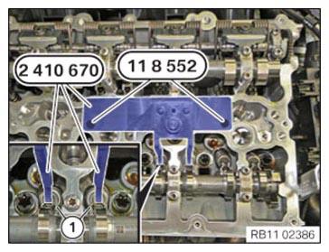
- Position the special tool 2 410 670 at cylinder 2 and hand-tighten it with the special tool 0 495 741 (11 8 552) from the set of special tools 0 495 739 (11 8 550).
- Screw in both roller cam followers (1) on 2nd cylinder with the spindle nut of the special tool 2 410 670
up to the limit position.
- Remove the roller tappet (1) from high pressure pump bracket (2).
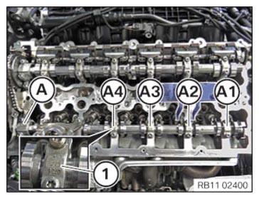
- Pay attention to the numbering on the exhaust camshaft bearing cap.
The exhaust camshaft bearing caps are numbered from (A1) till (A4).
The exhaust camshaft bearing cap (A) is a thrust bearing.
- Release screws in the right sequence (14) till (1) in semi circle pattern.
- Remove high pressure pump bracket and all exhaust camshaft bearing cap.
- Place all exhaust camshaft bearing cap in order in special tool 0 495 105 (11 4 480).
- (1) Remove exhaust camshaft in upward direction.
Remove all roller cam followers
- Detach and remove the roller cam followers (1) on the intake side from hydraulic valve clearance compensating elements (arrows).
- Place all the roller cam followers (1) in order in the special tool 0 495 105 (11 4 480).
- Detach and remove the roller cam followers (1) on the exhaust side from hydraulic valve clearance compensating elements (arrows).
- Place all the roller cam followers (1) in order in the special tool 0 495 105 (11 4 480).
Removing all hydraulic valve clearance compensating elements
- Remove all hydraulic valve clearance compensating elements (1) to the top.
- Lay the hydraulic valve clearance compensating elements, together with the rocker arms, orderly in the special tool 0 495 105 (11 4 480).
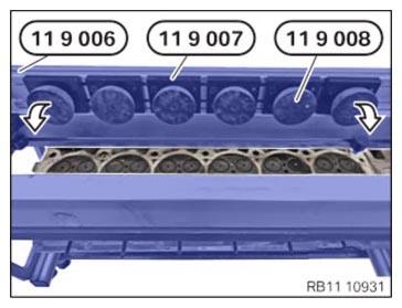
Removing valve springs
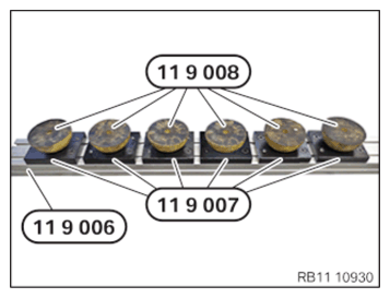
- Prepare the special tools 0 494 371 (11 9 006), 0 494 372 (11 9 007)
and 0 494 373 (11 9 008)
as shown.
- Position the special tools 0 494 371 (11 9 006), 0 494 372 (11 9 007)
and 0 494 373 (11 9 008)
in the direction of arrow in the center on the cylinder head.
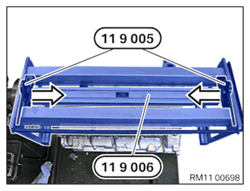
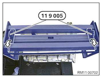
- Slide the special tool 0 494 370 (11 9 005)
in the direction of arrow over the edge of the special tool 0 494 371 (11 9 006).
- Lock special tool 0 494 370 (11 9 005) in arrow direction.
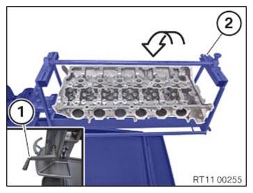
- Turn special tool 0 494 362 (11 9 000)
and the cylinder head by 180°.
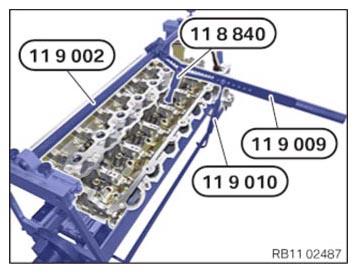
- Mount special tool 0 494 367 (11 9 002).
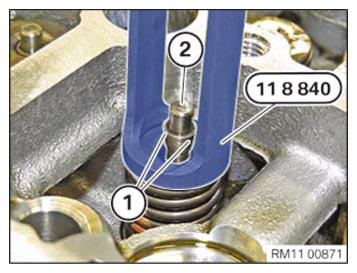
- Align special tool 0 494 374 (11 9 009) in direction of valve axis. Select the corresponding groove using special tool 0 496 143 (11 8 840).
- Press down the valve spring on the upper spring cup with the special tools 0 494 374 (11 9 009)
and 0 496 143 (11 8 840).
The valve spring can be maintained in pressed down installation position with the special tool 0 494 375 (11 9 011).
- Keep the valve spring pressed down with the special tool 0 496 143 (11 8 840).
- Remove the valve shims (1) from the valve (2) using a magnet.
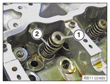
- Relieve load on valve spring.
- Remove the spring cup (1) and the valve spring (2) and position neatly in the special tool 0 495 105 (11 4 480).
Remove valve stem seals
NOTE: RISK OF DAMAGE
Contaminant or foreign body.
Contamination can result in malfunctions, loss of function or leaks.- Adhere to the utmost cleanliness.
- Protect components from contamination e.g. by covering.
- Close off line connections with seal plugs.
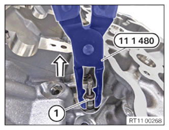
NOTE: The description is for one component only. The procedure is identical for all further components. - Remove the valve stem seal (1) in the arrow direction using the special tool 0 490 796 (11 1 480).
Remove all valves
NOTE: RISK OF DAMAGE
Contaminant or foreign body.
Contamination can result in malfunctions, loss of function or leaks.- Adhere to the utmost cleanliness.
- Protect components from contamination e.g. by covering.
- Close off line connections with seal plugs.
- B58:
Turn the special tool 0 494 366 (11 9 001) (2) on the crank (1) by 180° in arrow direction.
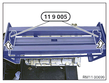
- Unlock the special tools 0 494 370 (11 9 005)
in arrow direction.
- B58:
Feed out and remove the special tools 0 494 371 (11 9 006), 0 494 372 (11 9 007) and 0 494 373 (11 9 008) in arrow direction.
- Slide the valve stem (1) in arrow direction
in the cylinder head.
- Remove the valve (1) and position in special tool 0 495 105 (11 4 480) in order.