Transmission, Installing
Special tools and workshop equipment required
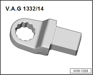
- Torque Wrench 1332 Insert - Ring Wrench - 16mm: VAG1332/14
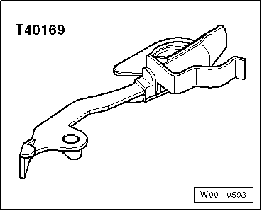
- Clutch Module Assembly Aid: T40169
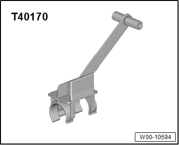
- Clutch Module Transportation Lock: T40170
- As well as all the special tools listed for the removal.
Procedure
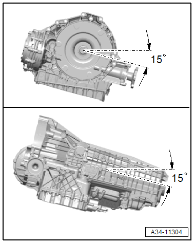
Risk of damaging the transmission by mixing ATF and transmission fluid (MTF) through the same bleeder.
- A transmission filled with ATF and MTF transmission fluid must not be tilted beyond a maximum of 15° in a lateral and or a longitudinal direction.
- If more of an incline is needed, then the ATF and (MTF) transmission fluids must be drained. Refer to ATF, DRAINING AND FILLING and Refer to TRANSMISSION FLUID, DRAINING AND FILLING .
Replace the bolts that were tightened with an additional turn.
Replace self-locking nuts and bolts, O-rings, sealing rings and seals.
Secure hose connections with hose clamps that correspond to the series production. Refer to the Parts Information.
During installation, all cable ties must be installed at the same location.
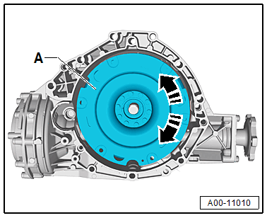
There is a normal >>clicking<< in the dual mass flywheel with "LuK" centrifugal pendulum absorber.
 Courtesy of AUDI OF AMERICA, LLC
A >>clicking<< is heard when turning -arrows- the clutch module -A- approximately every 90°. This noise comes from shifting pendulum masses (centrifugal pendulum absorber) in the dual mass flywheel and is not a fault.
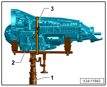
-- Mount the transmission onto the Gearbox Support: T40173A -2- and secure it using the tensioning strap -3- as shown.
-- The following preparations must be made before connecting the engine and transmission:
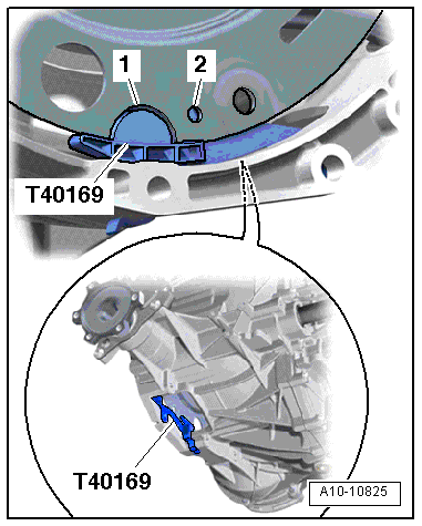
-- Insert the Clutch Module Assembly Aid: T40169 in the transmission housing and the flywheel from below as shown.
- The tool must grip into the semicircular hole and also in the hole -arrow A- and -arrow B-.
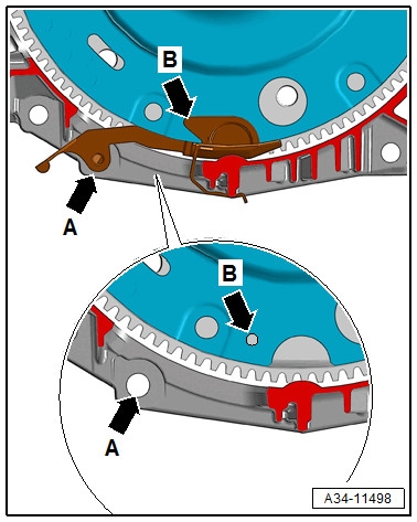
There is only one inspection opening -arrow B- on the edge. Rotate the flywheel as needed.
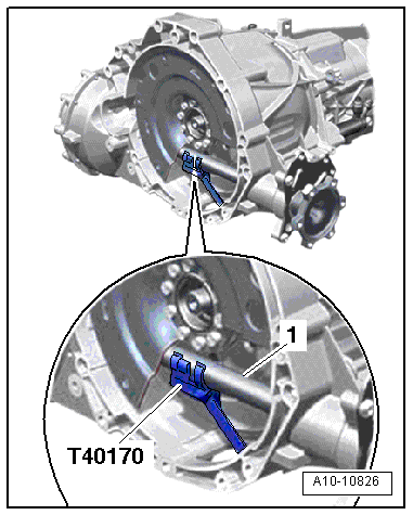
-- Insert the Clutch Module Transportation Lock: T40170 from below into the transmission housing and secure it to the flange shaft -1-.
-- Inspect the aluminum bolts used to connect the engine to the transmission to see if they can be used again and mark them, if necessary. Refer to The aluminum bolts may be used two times. Therefore, the bolts must be marked with two notches made by a chisel after they have be used the first time. .
Vehicles with Sealing Piece:
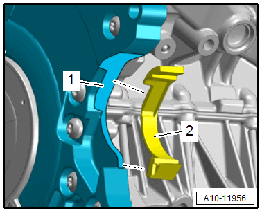
-- Clean the contact surface -1- on the lower timing chain cover and on the sealing piece -2- with Cleaning Solution: D 009 401 04 .
-- Bond the sealing piece to the lower timing chain cover.
Vehicles with 4-Cylinder Engine:
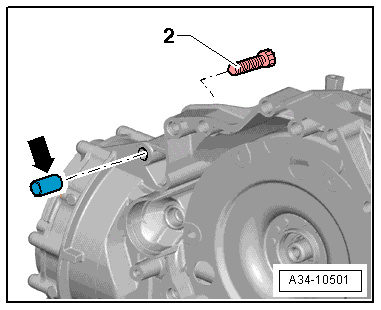
The bolt -2- attaches the starter to the transmission and has an additional spacer sleeve -arrow-.
The spacer sleeve must be inserted between the starter and the transmission.
-- Bring the starter into the installation position.
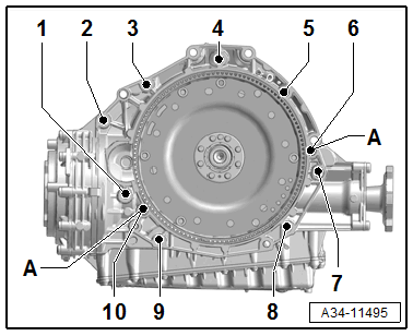
4-cylinder Vehicles 6-Cylinder TDI Engine:
 Courtesy of AUDI OF AMERICA, LLC
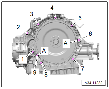
-- Check if that the alignment sleeves -A- for centering the engine and transmission are inserted in the cylinder block.
-- Place the transmission on the engine to do so guide the starter.
-- Tighten the bolt -8- hand-tight.
-- Install tunnel crossmember. Refer to OVERVIEW - ASSEMBLY MOUNTS .
-- Remove the extractor. Refer to ENGINE, SUPPORTING IN INSTALLATION POSITION 2.0L (DMSA) , ENGINE, SUPPORTING IN INSTALLATION POSITION 2.0L (DPAA) or ENGINE, SUPPORTING IN INSTALLATION POSITION 3.0L .
-- Tighten the bolts -1 to 10-.
4-Cylinder Vehicles TDI Engine:
 Courtesy of AUDI OF AMERICA, LLC
-- Check if that the alignment sleeves -A- for centering the engine and transmission are inserted in the cylinder block.
-- Place the transmission on the engine to do so guide the starter.
-- Tighten the bolt -7- by hand all the way.
-- Install tunnel crossmember. Refer to OVERVIEW - ASSEMBLY MOUNTS .
-- Remove the extractor. Refer to ENGINE, SUPPORTING IN INSTALLATION POSITION 2.0L (DMSA) , ENGINE, SUPPORTING IN INSTALLATION POSITION 2.0L (DPAA) or ENGINE, SUPPORTING IN INSTALLATION POSITION 3.0L .
-- Tighten bolts -1 through 9-.
All Vehicles:
Vibrations or rattling noises when driving!
- Always follow the step sequence, to guarantee that the vibration damper is assembled without tension.
- The vibration damper must rest flat on the drive plate when screwing in the first bolt.
-- Turn the crankshaft on the vibration damper 360° in the direction of engine rotation.
-- Remove the Clutch Module Transportation Lock: T40170 .
If the vibration damper -1- does not lay flat on the drive plate, insert the Clutch Module Transportation Lock: T40170 and turn the crankshaft another 360°.
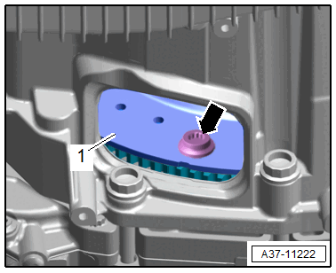
-- Install the first bolt -arrow-, tighten to 10 Nm, loosen and then tighten to 2 Nm (hand-tight).
-- Remove the Clutch Module Assembly Aid: T40169 .
-- Tighten the flywheel to the drive plate as follows:
Vehicle with 4-Cylinder Engine (Three Bolts):
-- Turn the crankshaft on the vibration damper 120° in the direction of the engine rotation with a large offset open-end wrench.
-- Install the next bolt in this crankshaft stub and tighten. Refer to TRANSMISSION TIGHTENING SPECIFICATIONS .
-- Turn the crankshaft another 120° in the direction of engine rotation and install the next bolt and tighten.
-- Turn the crankshaft another 120° in the direction of engine rotation and tighten the last bolt.
Vehicle with 6-Cylinder Engine (Six Bolts):
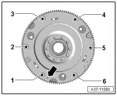
-- Turn the crankshaft on the vibration damper 180° in the direction of engine rotation, install bolt -4- and tighten. Refer to OVERVIEW - FLYWHEEL AND DUAL CLUTCH .
-- Turn the crankshaft another 60° in the direction of engine rotation, install bolts -5 and 6- and tighten.
-- Turn the crankshaft another 60° in the direction of engine rotation and tighten bolt -1-.
-- Turn the crankshaft another 60° in the direction of engine rotation, install bolts -2 and 3- and tighten.
All Vehicles:
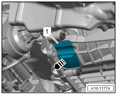
-- Install the cover -1-.
Install in reverse order of removal. Note the following:
-- Connections and routing. Refer to the appropriate Wiring Diagram.
-- Tighten the drive axles. Refer to OVERVIEW - DRIVE AXLE .
-- Install the drive axle heat shield. Refer to DRIVE AXLE HEAT SHIELD, REMOVING AND INSTALLING .
-- Install the drive axle cover. Refer to OVERVIEW - FRONT WHEEL HOUSING LINER .
-- Install the front wheels. Refer to the appropriate Service Information .
-- Install the parking lock emergency release cable. Refer to PARKING LOCK EMERGENCY RELEASE CABLE, REMOVING AND INSTALLING .
-- Install the coolant pipe for the transmission. Refer to OVERVIEW - COOLANT PIPES 2.0L (DMSA) , OVERVIEW - COOLANT PIPES 2.0L (DPAA) or OVERVIEW - COOLANT PIPES 3.0L .
-- Install the steering intermediate shaft. Refer to STEERING INTERMEDIATE SHAFT, REMOVING AND INSTALLING .
-- Install the driveshaft. Refer to DRIVESHAFT, REMOVING AND INSTALLING .
-- Install the emissions control module. Refer to the appropriate Service Information .
-- Install the front exhaust pipe. Refer to OVERVIEW - MUFFLER - 2.0L (DMSA) , OVERVIEW - MUFFLER - 2.0L (DPAA) or OVERVIEW - MUFFLER - 3.0L .
-- Install the subframe crossbrace. Refer to SUBFRAME CROSSBRACE, REMOVING AND INSTALLING .
-- Bleed the cooling system if the drained coolant is less than or equal to 0.5 Liter, otherwise fill and bleed the cooling system. Refer to COOLANT, DRAINING AND FILLING 2.0L (DMSA) , COOLING SYSTEM/COOLANT 2.0L (DPAA) , or COOLANT, DRAINING AND FILLING 3.0L .
-- Install the engine cover. Refer to ENGINE COVER, REMOVING AND INSTALLING 2.0L (DMSA) , ENGINE COVER, REMOVING AND INSTALLING 2.0L (DPAA) or ENGINE COVER, REMOVING AND INSTALLING 3.0L .
-- Follow all steps after connecting the battery. Refer to BATTERY, DISCONNECTING AND CONNECTING .
-- Check the MTF level and correct if necessary. Refer to TRANSMISSION FLUID LEVEL, CHECKING .
-- Check the ATF level and correct if necessary. Refer to ATF LEVEL, CHECKING .
If a new factory transmission is installed, an MTF/ATF level test is not necessary.
If the transmission is replaced, the "Replace control module" function must be performed using the Vehicle Diagnostic Tester.
Procedure
-- Connect the Vehicle Diagnostic Tester.
-- Select Diagnostic mode and start the diagnostic.
-- Select the Test plan tab.
-- Select individual test button and select the following tree structure one after the other:
- Drivetrain
- 7-Speed Dual Clutch Transmission 0CJ, 0CK, 0CL, 0DN, 0DP
- 01 - OBD-capable systems
- 02 - Transmission electronics
- 02 - Transmission electronics, functions
- 02 - Replace control module → Entire transmission
-- Start the selected program and follow the instructions in the display of the Vehicle Diagnostic Tester.