MECHATRONIC, Removing And Installing: Installing
Install in the reverse order of removal while noting the following:
Risk of damaging the ATF pump.
- The pump for the Transmission Fluid Auxiliary Hydraulic Pump -V552- can start up on a non-deactivated control module immediately after installing the connector.
- The pump can be damaged, by this or the residual oil can flow out under high pressure.
- To prevent this install the transmission control module connector after installing the oil pan and the transmission filled with ATF.
- Only install clean parts: remove the new mechatronic from the packaging immediately prior to installation.
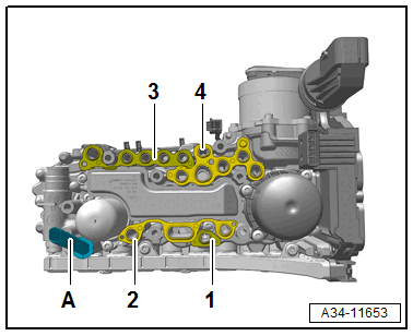
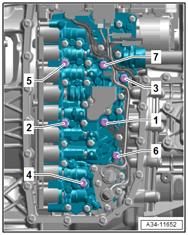
-- Replace the seals -1, 2, 3 and 4-.
Tip:
- The seal -1- is only for vehicles with a Parking Lock Solenoid -N486-.
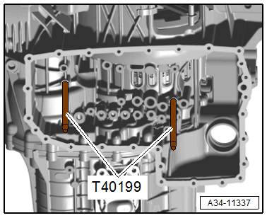
The Oil Sump Assembly Pin: T40199 prevent the Mechatronic from tilting when it is being installed.
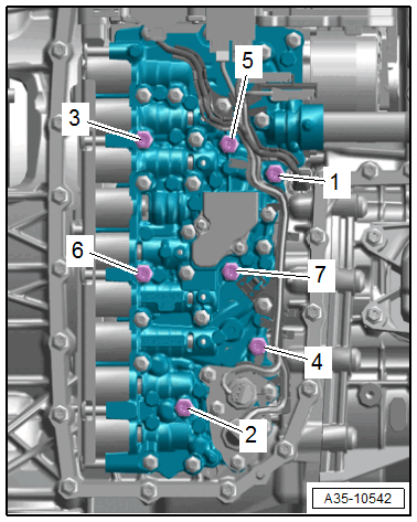
-- Replace the Mechatronic evenly and install the bolts -6 and 7- hand-tight.
-- Remove the Oil Sump Assembly Pin: T40199 .
-- Install the remaining bolts according to the tightening sequence. Refer to Figure.
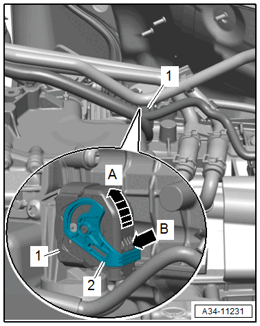
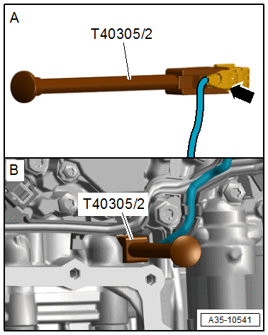
-- Install the connector with the Assembly Tool: T40305 .
-- Install the transmission fluid pan. Refer to TRANSMISSION FLUID PAN, REMOVING AND INSTALLING .
-- Tighten the ATF drain plug.
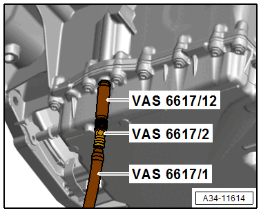
-- Fill 3.5 liters of AFT in the transmission using the Pressurized Gearbox Oil Filler Kit: VAS 6617 . Refer to ATF, DRAINING AND FILLING .
Tip:
- The ATF level can be adjusted after operating the control module.
- For the following components after replacing a set up must be performed:
- Transmission Control Module -J217-
- Valve Body --
- Dual-Clutch Transmission Mechatronic -J743-
- Drive Position Sensor -G676-. Refer to Parking Lock Solenoid -N486- /Drive Position Sensor -G676-, REMOVING AND INSTALLING .
- Transmission Fluid Auxiliary Hydraulic Pump -V552-. Refer to Calibrating the auxiliary hydraulic pump .
- Gear Position Distance Sensors 1 to 4 -G487/G488/G489/G490-. Refer to GEAR ACTUATOR MODULE AND HYDRAULIC PRESSURE RESERVOIR, REMOVING AND INSTALLING .
- Automatic Transmission Pressure Regulating Valve 1 and 2 -M215/N216-. Refer to Clutch Valve Calibration .
- Solenoid Valves and Pressure Regulating Valves in Valve Body --. Refer to Cooling Oil/Clutch Calibration .
-- Connect the Vehicle Diagnostic Tester with the vehicle.
- Network plan or control module list
- 02 - Transmission Electronics, Guided Functions
- 02 - Control Modules/Mechatronic, Replacing
-- Start the selected program and follow the instructions in the display of the Vehicle Diagnostic Tester.
-- Checking the ATF level. Refer to ATF LEVEL, CHECKING .
-- Install the subframe crossbrace. Refer to SUBFRAME CROSSBRACE, REMOVING AND INSTALLING .
-- Install the noise insulation. Refer to NOISE INSULATION, REMOVING AND INSTALLING .