Engine, Installing, Vehicle With High-Voltage System
Special tools and workshop equipment required
- All special tools listed when removing the engine
Procedure
- Replace bolts that were tightened with an additional turn after removing them.
- Replace the self-locking nuts and bolts, gaskets, seals and O-rings after removing.
- Only remove the plugs or caps just before installing the respective lines.
- Secure all hose connections with hose clamps that match the ones used in series production. Refer to the Parts Information.
- During installation, all cable ties must be installed at the same location.
- Used coolant cannot be used again.
TIP:
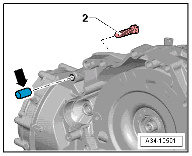
The bolt -2- attaches the starter to the transmission and has an additional spacer sleeve -arrow-.
- The spacer sleeve must be inserted between the starter and the transmission.
-- Install the transmission on the engine. Refer to TRANSMISSION, INSTALLING .
-- Move the engine with the transmission in installation position.
-- Install the emergency release cable for the parking lock. Refer to OVERVIEW - PARKING LOCK EMERGENCY RELEASE .
-- Install the tunnel crossmember. Refer to OVERVIEW - ASSEMBLY MOUNTS .
-- Install the catalytic converter. Refer to CATALYTIC CONVERTER, REMOVING AND INSTALLING .
-- Install the particulate filter. Refer to PARTICULATE FILTER, REMOVING AND INSTALLING .
-- Install the A/C compressor. Refer to A/C COMPRESSOR, REMOVING AND INSTALLING FROM BRACKET .
-- Install the drive axles. Refer to OVERVIEW - DRIVE AXLE .
-- Install the subframe. Refer to SUBFRAME WITH STEERING GEAR, REMOVING AND INSTALLING .
-- Install the air filter housing. Refer to OVERVIEW - AIR FILTER HOUSING .
-- Connections and wire routing. Refer to the appropriate Wiring Diagram.
- High-voltage cables disconnected from the power electronics.
-- After installing high-voltage components or potential equalization cables a potential equalization measurement must be performed on the applicable high-voltage components. Refer to POTENTIAL EQUALIZATION MEASUREMENT .
-- Install the high-voltage cables. Refer to COMPONENT LOCATION OVERVIEW - HIGH-VOLTAGE CABLES .
-- Connect the fuel hose. Refer to CONNECTOR COUPLINGS, DISCONNECTING .
-- Install the front muffler. Refer to FRONT MUFFLER, REMOVING AND INSTALLING .
-- Install the exhaust system without tension. Refer to EXHAUST SYSTEM, INSTALLING WITHOUT TENSION .
-- Install the coolant pipes. Refer to OVERVIEW - COOLANT PIPES, VEHICLE WITH HIGH-VOLTAGE SYSTEM .
-- Install the bumper cover end plate and the lock carrier cover. Refer to OVERVIEW - BUMPER COVER .
-- Install the driveshaft. Refer to DRIVESHAFT, REMOVING AND INSTALLING .
-- Install the front lower longitudinal member. Refer to OVERVIEW - LOCK CARRIER .
-- Install the wheel housing liners and wheel spoilers. Refer to OVERVIEW - FRONT WHEEL HOUSING LINER .
-- Install the front wheels. Refer to the appropriate Service Information .
-- Remove the front fender covers. Refer to OVERVIEW - FENDER .
-- Install the noise insulation. Refer to OVERVIEW - NOISE INSULATION .
-- Fill the engine oil and check the oil level. Refer to ENGINE OIL .
-- Install the engine cover. Refer to ENGINE COVER, REMOVING AND INSTALLING .
-- Follow all steps after connecting the 12V battery. Refer to BATTERY, DISCONNECTING AND CONNECTING .
There is a risk of fatal injury due to high voltage.
Electrocution by direct contact or electric arc can cause severe bodily injury or fatal injury.
- Have an Audi high-voltage technician or an Audi high-voltage expert bring the high-voltage system back into service.
-- Re-energize the high-voltage system. Refer to HIGH-VOLTAGE SYSTEM, RE-ENERGIZING .
There is a risk of destroying the control modules due to excessive voltage.
- Do not use a battery charger to jump start!
After Replacing the Engine an Adaptation must be Preformed.
-- Perform the adaptations. Refer to PERFORM ADAPTATIONS AFTER COMPONENT REPLACEMENT .
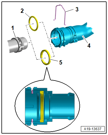
-- Connect the coolant hose to the connector coupling. Refer to Fig 2.
-- Fill the cooling system. Refer to COOLANT, FILLING USING Cooling System Charge Kit: VAS6096 [DMTA, DPAA, DPUA, DPVA, DMTC, DRYA, DUVA] .
Tightening Specifications
- The tightening specifications only apply to lightly greased, oiled, phosphated or blackened nuts and bolts.
- Additional lubricants, such as engine or transmission oil are permissible, although lubricants containing graphite are not.
- Do not use any ungreased parts.
- Tightening specification tolerance: ±15%.
| Component | Nm | ||
|---|---|---|---|
| Bolts and nuts | M6 | 9 | |
| M7 | 15 | ||
| M8 | 20 | ||
| M10 | 40 | ||
| M12 | 65 | ||