Replacing the coolant hose of the return line of the exhaust turbocharger
WARNING:
Hot fluids.
Risk of scalding!
Risk of scalding!
- Conduct all work in the vehicle wearing appropriate personal protective equipment only.
WARNING:
Hot surfaces.
Risk of burning!
Risk of burning!
- Perform all work only on components that have cooled down.
NOTE:
Collect and dispose of emerging fluids. Observe country-specific waste disposal regulations.
Preliminary work
- Refer to REMOVING THE ACOUSTIC COVER .
- Refer to REMOVING INTAKE SILENCER HOUSING .
- Refer to REMOVING THE RESONATOR WITH THE TOP CLEAN AIR PIPE .
- Refer to REMOVING THE COVER ON LEFT AND RIGHT IN THE ENGINE COMPARTMENT AT THE TOP .
- Refer to REMOVING THE LEFT AND RIGHT FRONT-END STRUT .
- Refer to REMOVING FRONT CROSS CONNECTION .
- Refer to REMOVING THE REAR TOP CROSS CONNECTION .
- Refer to REMOVING THE FAN COWL .
- Refer to REMOVING THE FRONT UNDERBODY PROTECTION OR FRONT THRUST FIELD .
- Refer to REMOVING THE STIFFENING PLATE .
- Refer to REMOVING THE CONNECTING SUPPORT FROM THE TUNNEL .
- Refer to REMOVING COMPLETE EXHAUST SYSTEM .
- Refer to REPLACING THE LAMBDA OXYGEN SENSOR .
- Refer to REPLACING THE OXYGEN MONITOR SENSOR .
- Refer to DRAINING THE COOLANT FROM THE HIGH-TEMPERATURE COOLING SYSTEM .
- Refer to REMOVING CATALYTIC CONVERTER .
NOTE:
Collect and dispose of emerging fluids. Observe country-specific waste disposal regulations.
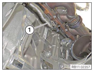
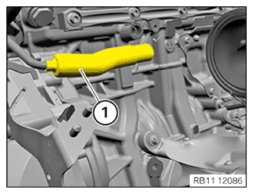
- Slide heat protection (1) carefully backwards.
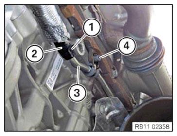
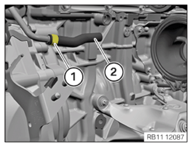
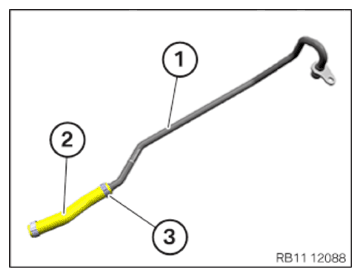
- Release the hose clamp (1) and detach the coolant return line (2) from the coolant return line (3).
- Loosen screw (4).
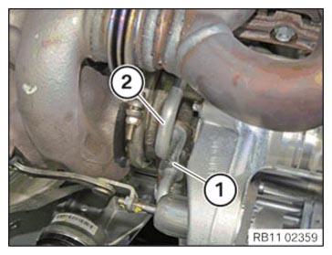
- Loosen screw (1).
- Disconnect the coolant return line (2) from the exhaust turbocharger.
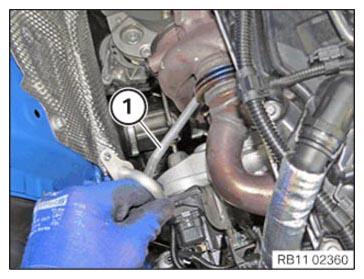
- Feed the front section of the coolant return line (1) out to the front and top.
- Remove the previous heat shield (1).
- Cut through the circlip (1) with a suitable tool.
- Make sure that the coolant return line (rear section) is not damaged.
- Detach and remove the previous coolant hose (2).
- Carefully slide the new heat shield (1) onto the coolant return line (rear section).
Parts: Heat shield
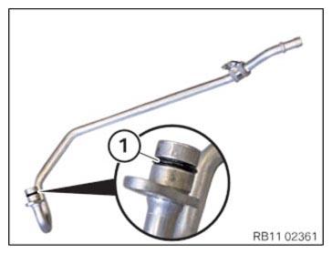
- Replace O-ring (1).
Parts: O-ring
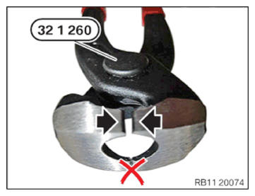
- To fasten the circlips, use special tool 0 494 152 (32 1 260) exclusively.
- Crimp the circlips with the slightly open side (arrows).
The circlip is crimped properly if the gap is less than 1 mm.
- Push the new coolant hose onto the front section of the coolant return line (1).
Parts: Coolant hose
- Push the new circlips onto the coolant hose.
Parts: Clamps
- Fasten the coolant hose (2) only with the circlip (3) on the front section of the coolant return line (1).
- To squeeze the circlip, use special tool 0 494 152 (32 1 260).
- Feed in the front section of the coolant return line (1) from the top.
- Connect the coolant return line (2) to the exhaust turbocharger.
- Tighten down screw (1).TIGHTENING TORQUES SPECIFICATION
Coolant feed line/coolant return line to exhaust turbocharger M6 x 12 tightening torque 8 Nm - Make sure that the coolant return line is routed correctly between the heat shield of the exhaust turbocharger and the trim strip on the exhaust manifold and the exhaust turbocharger respectively.
- Push the front section of the coolant return line (1) with the coolant hose (2) onto the rear section of the coolant return line.
- Fasten the coolant hose (2) with the hose clamp (3).
- To squeeze the circlip, use special tool 0 494 152 (32 1 260).
- Tighten down screw (4).

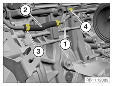
TIGHTENING TORQUES SPECIFICATION
| Coolant return line to trim strip | ||
| M6 x 12 | tightening torque | 8 Nm |
- Make sure that the new heat shield (1) is not cracked or otherwise damaged, replace if necessary.
- Push the heat shield (1) to the front.
The heat shield (1) must cover the entire hose of the coolant line.
Follow-up work
- Refer to INSTALLING CATALYTIC CONVERTER .
- Refer to CONNECTING THE COOLANT LINES FOR THE HIGH-TEMPERATURE COOLANT CIRCUIT .
- Refer to FILLING THE HIGH-TEMPERATURE COOLING SYSTEM WITH THE VACUUM FILLING EQUIPMENT .
- Refer to INSTALLING THE OXYGEN SENSOR MONITOR .
- Refer to INSTALLING LAMBDA OXYGEN SENSOR .
- Refer to PREPARING THE EXHAUST SYSTEM .
- Refer to INSTALLING THE COMPLETE EXHAUST SYSTEM .
- Refer to INSTALLING THE CONNECTING SUPPORTS ON THE TUNNEL .
- Refer to INSTALLING FAN COWL .
- Refer to INSTALLING THE REAR TOP CROSS CONNECTION .
- Refer to INSTALLING FRONT CROSS CONNECTION .
- Refer to INSTALLING FRONT-END STRUT ON LEFT AND RIGHT .
- Refer to INSTALLING THE COVER ON THE LEFT AND RIGHT IN THE ENGINE COMPARTMENT AT THE TOP .
- Refer to INSTALLING THE RESONATOR WITH THE TOP CLEAN AIR PIPE .
- Refer to INSTALLING INTAKE SILENCER HOUSING .
- Refer to INSTALLING ACOUSTIC COVER .
- Refer to INSTALLING THE THRUST FIELD .
- Refer to INSTALLING THE FRONT UNDERBODY PROTECTION OR FRONT THRUST FIELD .
- Refer to VENTING THE HIGH-TEMPERATURE COOLANT SYSTEM .