Installing automatic transmission (all-wheel drive vehicle) (GA8HP51Z)
NOTE:
RISK OF DAMAGE
Damage to the transmission.
Damage to the transmission due to unapproved transmission oil.
Damage to the transmission.
Damage to the transmission due to unapproved transmission oil.
- Use only the approved TRANSMISSION OIL .
- Check the transmission OIL LEVEL after completing the repair.
NOTE:
TECHNICAL INFORMATION
After completion of the work, program the control unit for the electronic gearbox control (EGS).
After completion of the work, program the control unit for the electronic gearbox control (EGS).
Checking installation position of torque converter
NOTE:
RISK OF DAMAGE
Damage to the automatic transmission/impeller.
When disconnecting the engine and transmission, the torque converter can become loose! Failure to observe the correct installation positions of the torque converter may lead to damage to the impeller driver.
Damage to the automatic transmission/impeller.
When disconnecting the engine and transmission, the torque converter can become loose! Failure to observe the correct installation positions of the torque converter may lead to damage to the impeller driver.
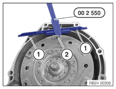
- Make sure that the torque converter is in the correct installation position before installing the automatic transmission.
- Check the installation dimension between the contact surfaces (1) and the outer edge (2) of the threaded hole of the torque converter with the special tool 0 490 189 (00 2 550) .
- See REPAIR INSTRUCTIONS -Removing and installing/replacing torque converter
NOTE:
RISK OF DAMAGE
Damage of the flywheel and automatic transmission.
A non-horizontal fit during the removal and installation of the automatic transmission can lead to damage on the automatic transmission or flywheel.
Damage of the flywheel and automatic transmission.
A non-horizontal fit during the removal and installation of the automatic transmission can lead to damage on the automatic transmission or flywheel.
- Align the automatic transmission completely horizontal to the engine during the removal and installation.
- Check for correct alignment before tightening the transmission bolts.
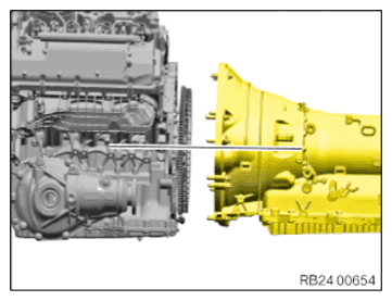
- Before installing the automatic transmission, align it horizontally to the engine.
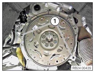
- Check the fitting sleeves (1) for correct fit and damage and replace as needed.
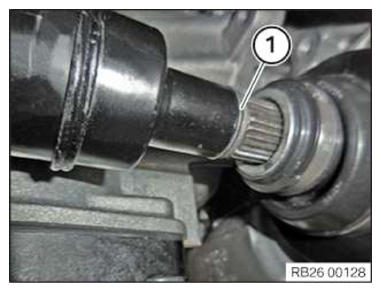
- Replace O-ring (1).
The O-ring must be replaced before installing the front prop shaft in the transfer box (VTG).
Parts: O-ring
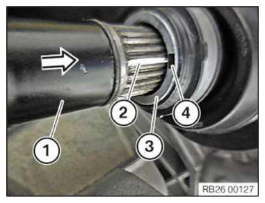
- Position the front prop shaft (1) on the output flange (3) of the transfer box (VTG).
- Align the marks (2) and (4) of the front prop shaft (1).
- Slide the front prop shaft (1) up to the stop into the output flange (3) of the transfer box.
- Flange-mount the transmission on the transfer box (VTG).
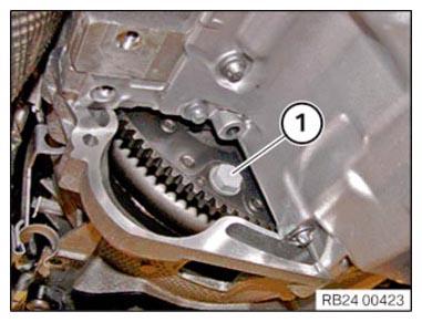
- Turn the torque converter until the bore of the torque converter is aligned with the bore of the drive plate.
- Fit the transmission bolts (arrows) and apply lightly.
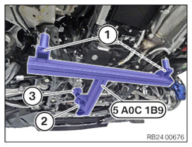
- Turn the knurled screw (2) until the plate (3) is no longer in contact.
- Release screws (1) and remove the special tool 5A0C1B9 .
- Replace screws (1).
Parts: Screws
- Tighten the screws (1) on the front axle support.
TIGHTENING TORQUES SPECIFICATION
| Front axle carrier to body, rear | ||
|---|---|---|
| M14 Replace screws. |
Joining torque | 108 Nm |
| Angle of rotation | 45° | |
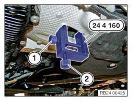
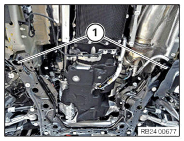
- Release screw (1) and screw (2).
- Remove the special tool 0 494 451 (24 4 160).
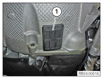
- Install the sealing cap (1).
- Replace screws.
Parts: Screws
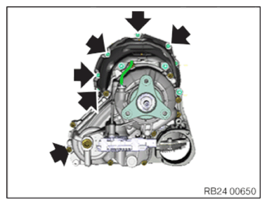
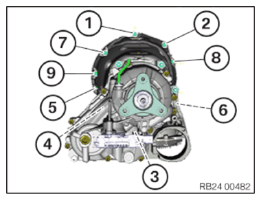
- Turn the engine in the direction of rotation using special tool 0 493 380 (11 6 480) on the vibration damper to tighten all 6 screws (1).
- Tighten all 6 screws (1) of the torque converter using special tool 0 491 667 (24 1 110).
TIGHTENING TORQUES SPECIFICATION
| Torque converter to flywheel | ||
|---|---|---|
| M10 Replace screws. |
Tightening torque | 56 Nm |
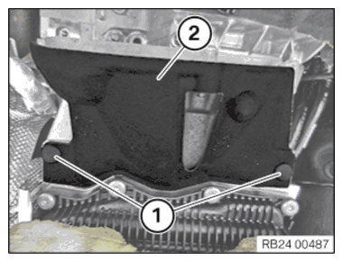
- Install acoustic cover (2).
- Install the expanding rivets (1).
- Install the exhaust bracket (2).
- Tighten down screws (1).
TIGHTENING TORQUES SPECIFICATION
| Transmission to engine | ||
|---|---|---|
| M8 | Tightening torque | 19 Nm |
| M12 | Tightening torque | 66 Nm |
- Tighten nuts (1).
TIGHTENING TORQUES SPECIFICATION
| Catalytic converter to holder | ||
|---|---|---|
| M8 copper-plated nut Replace nut. | Tightening torque | 28 Nm |
| M8 zinc-plated nut | Tightening torque | 19 Nm |

- Remove the special tool 0 494 213 (24 2 390) from the sealing sleeve in the arrow direction.
NOTE:
TECHNICAL INFORMATION
Notes on mechatronics are a fundamental requirement for these repair instructions and must be complied with at all times.
Notes on mechatronics are a fundamental requirement for these repair instructions and must be complied with at all times.
For ADDITIONAL INFORMATION see: 24 34... Notes on mechatronics (GA8HP50Z/GA8HP51Z/GA8HP75Z/GA8HP
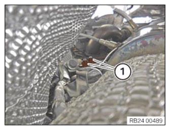
- Slide connector (1) in the arrow direction and lock it by turning it.
- Tighten the transmission bolts in the sequence (1) to (9).
TIGHTENING TORQUES SPECIFICATION
| Transmission to engine | ||
|---|---|---|
| M8 | Tightening torque | 19 Nm |
| M12 | Tightening torque | 66 Nm |
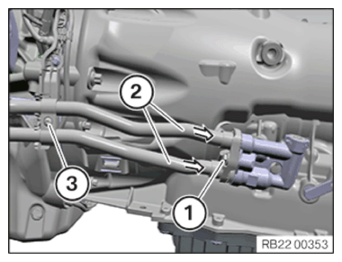
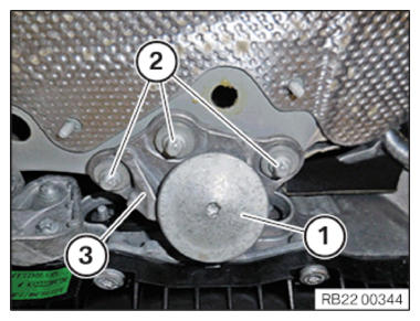
- Replace sealing rings.
Parts: Sealing ring
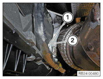
- Install hydraulic lines (2) on transmission in arrow direction.
- Position and tighten the screw (1).
TIGHTENING TORQUES SPECIFICATION
| Transmission oil line to transmission | ||
|---|---|---|
| M6x25 Replace the sealing ring. | Tightening torque | 8 Nm |
- Position and tighten the screw (3).
TIGHTENING TORQUES SPECIFICATION
| Transmission oil line on holder | ||
|---|---|---|
| M6 | Tightening torque | 4 Nm |
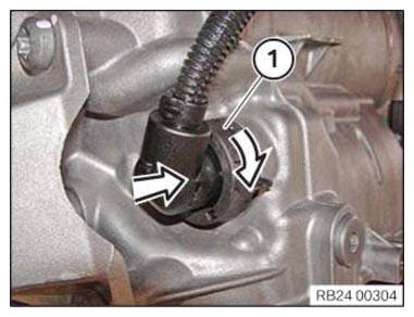
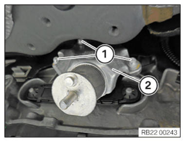
- Connect the connector (1) to the VTG control unit for the longitudinal torque distribution (2).
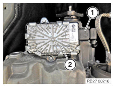
- Guide in and install wiring harness section (3) of the supply module.
- Tighten down screw (1).
TIGHTENING TORQUES SPECIFICATION
| Grounding cable to transmission | ||
|---|---|---|
| M6 | Tightening torque | 8 Nm |
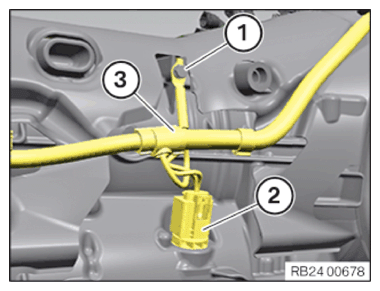
- Connect connectors (2) and lock.
The connector (2) must engage audibly.
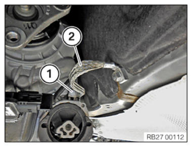
- Install the ground strap (2).
- Tighten down screw (1).
TIGHTENING TORQUES SPECIFICATION
| Ground strap to transmission or body | ||
|---|---|---|
| M8 | Tightening torque | 19 Nm |
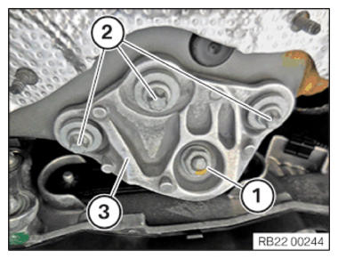
- Remove transmission mounting bracket (2) on the right transmission side.
- Replace screws (1).
Parts: Screws
- Tighten down screws (1).
TIGHTENING TORQUES SPECIFICATION
| Transmission mounting bracket to transmission | ||
|---|---|---|
| M8 Replace screws. |
Tightening torque | 28 Nm |
- Version A:
- Install transmission bearing support holder (3).
- Tighten down screws (2).
TIGHTENING TORQUES SPECIFICATION
| Transmission bearing support to body | ||
|---|---|---|
| M8 | Tightening torque | 19 Nm |
- Tighten the vibration absorber (1).
TIGHTENING TORQUES SPECIFICATION
| Rubber mount to transmission bearing support | ||
|---|---|---|
| M8 | Tightening torque | 19 Nm |
- Version B:
- Install transmission bearing support holder (3).
- Tighten down screws (2).
TIGHTENING TORQUES SPECIFICATION
| Transmission bearing support to body | ||
|---|---|---|
| M8 | Tightening torque | 19 Nm |
- Tighten nut (1).
TIGHTENING TORQUES SPECIFICATION
| Rubber mount to transmission bearing support | ||
|---|---|---|
| M8 | Tightening torque | 19 Nm |
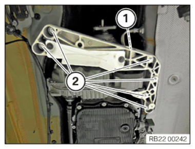
- Install the transmission cross member.
- Tighten down screws (2).
TIGHTENING TORQUES SPECIFICATION
| Transmission cross member to body | ||
|---|---|---|
| M8 | Tightening torque | 19 Nm |
- Tighten down screw (1).
TIGHTENING TORQUES SPECIFICATION
| Transmission cross member to rubber mounts | ||
|---|---|---|
| M12 | Tightening torque | 68 Nm |
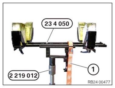
- Release the luggage strap (1) from the transmission.
- Remove the special tools 0 495 498 (23 4 050) and 2 219 012 from the transmission.
Follow-up work
- Fasten the (partially removed) PROP SHAFT
- Install the RETAINING PLATES .
- Install the HEAT SHIELDS .
- Install the complete EXHAUST SYSTEM .
- Install the tunnel connecting SUPPORTS .
- If installed: install the right and left TORSION STRUT where required.
- Install the THRUST FIELD .
- Install the UNDERBODY PROTECTION of the steering gear or the front thrust field.
- Install the front UNDERBODY PROTECTION or front thrust field.
- Reconnect all battery GROUND LEADS .
- Check/top up the automatic transmission OIL LEVEL .
- Install rear UNDERBODY PROTECTION .
- Install the transmission side UNDERBODY PLANKING .
- If the active stabilizer is installed: install fan COWL .
- Activate the 48 v ELECTRICAL SYSTEM .