Installing the oil pan
Follow-up work
- Refer to INSTALLING STARTER MOTOR .
- Refer to INSTALLING THE ACOUSTIC COVER FOR THE OIL PAN .
- Refer to RAISE FRONT AXLE SUPPORT .
- Refer to TIGHTEN THE SCREWS ON THE LEFT AND RIGHT FRONT AXLE SUPPORT .
- Refer to SECURE THE SPRING STRUT ON THE WISHBONE ON THE BOTTOM LEFT AND RIGHT .
- Refer to SECURE THE WISHBONE ON THE TOP LEFT AND RIGHT ON THE SWIVEL BEARING .
- Refer to REMOVING THE MOBILE LIFTING TABLE .
- Refer to ATTACHING COOLANT HOSES TO FRONT SUBFRAME .
- Refer to ATTACHING THE UNIVERSAL JOINT TO STEERING GEAR .
- Refer to IF INSTALLED: SECURING THE LINE FOR THE VERTICAL ACCELERATION SENSOR ON THE RIGHT AND LEFT .
- Refer to ATTACHING THE CABLE OF THE WHEEL RPM SENSOR ON THE LEFT AND RIGHT .
- Refer to CLIP THE BRAKE HOSES ON THE FRONT RIGHT AND LEFT .
- Refer to IF INSTALLED: CONNECT THE CONNECTOR OF THE ACTIVE STABILIZER
- Refer to IF INSTALLED: INSTALL THE SILENCER OF THE STATIONARY HEATING (ADDITIONAL WORK FRU NO.: 3111 905) .
- Refer to INSTALL THE WHEEL ARCH COVER ON THE FRONT LEFT AND BOTTOM RIGHT
- Refer to INSTALL THE REAR SECTION OF THE FRONT WHEEL ARCH COVER ON THE LEFT AND RIGHT .
- Refer to INSTALL LEFT AND RIGHT BRAKE VENTILATION DUCT .
- Refer to SECURE THE WIRING HARNESS FOR THE EPS ON THE FRONT AXLE SUPPORT .
- Refer to INSTALL THE REINFORCEMENT STRUT ON THE RIGHT ENGINE MOUNT .
- Refer to INSTALL THE COVER OF THE STEERING ASSEMBLY ON THE LEFT AND RIGHT .
- Refer to INSTALL THE FRONT LEFT AND RIGHT WHEELS .
- Refer to LOWERING THE ENGINE AND DETACHING THE ENGINE BRIDGE .
- Refer to FASTENING THE ENGINE SUPPORT BRACKETS ON THE ENGINE MOUNTS ON THE LEFT AND RIGHT .
- Refer to INSTALLING THE MOUNT OF THE HOOD SEAL .
- Refer to INSTALLING THE COVER ON THE LEFT AND RIGHT IN THE ENGINE COMPARTMENT AT THE TOP
- Refer to REMOVING SPECIAL TOOL FROM THE CYLINDER HEAD .
- Refer to INSTALL RESONATOR .
- Refer to TOPPING UP THE MOTOR OIL .
- Refer to CONNECTING NEGATIVE BATTERY CABLE .
- Refer to ACTIVATING THE 48 V ELECTRICAL SYSTEM .
- Refer to INSTALL THE REAR RIGHT ENGINE COMPARTMENT COVER .
- Refer to INSTALL THE COVER OF THE ENGINE COMPARTMENT ON THE REAR LEFT .
- Refer to INSTALL ACOUSTIC COVER .
- Refer to CHECK ENGINE OIL LEVEL .
- Refer to INSTALL THE CENTER UNDERBODY PROTECTION .
- Refer to INSTALLING THE UNDERBODY PROTECTION OF THE STEERING GEAR OR THE FRONT THRUST FIELD .
- Refer to INSTALL THE FRONT UNDERBODY PROTECTION OR FRONT THRUST FIELD .
- Refer to INSTALL REAR UNDERBODY PROTECTION .
- Refer to TAKE HOOD OUT OF THE SERVICE POSITION .
Further information is available.
NOTE:
RISK OF DAMAGE
Contaminant or foreign body.
Contamination can result in malfunctions, loss of function or leaks.
Contaminant or foreign body.
Contamination can result in malfunctions, loss of function or leaks.
- Adhere to the utmost cleanliness.
- Protect components from contamination e.g. by covering.
- Close off line connections with seal plugs.
NOTE:
RISK OF DAMAGE
Damage to the surface.
The use of metal-cutting tools (e.g., emery cloths) for cleaning surfaces can damage them and lead to leaks and/or engine damage.
Damage to the surface.
The use of metal-cutting tools (e.g., emery cloths) for cleaning surfaces can damage them and lead to leaks and/or engine damage.
- Do not use any metal-cutting tools.
NOTE:
TECHNICAL INFORMATION
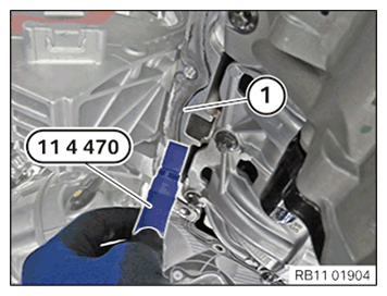
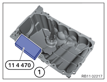
The sealing surfaces must be free of oil, grease and cleaning agents.
The sealing surfaces must be free of oil, grease and cleaning agents.
- Remove fine seal remains on the sealing surface (1) of the oil pan with the special tool 0 495 102 (11 4 470) .
- Clean sealing surface (1)
.CONSUMABLE - BRAKE CLEANER DESCRIPTION
Brake cleaner 2.0 500 ml, Spray can 83192365214 20, Canister 83192365215 NOTE: RISK OF DAMAGE
Damage to the surface.
The use of metal-cutting tools (e.g., emery cloths) for cleaning surfaces can damage them and lead to leaks and/or engine damage.- Do not use any metal-cutting tools.
NOTE: TECHNICAL INFORMATION
The sealing surfaces must be free of oil, grease and cleaning agents. - Remove rough seal remains on the sealing surface (1) of the crankcase with the special tool 0 495 102 (11 4 470) .
- Clean sealing surface (1)
.CONSUMABLE - BRAKE CLEANER DESCRIPTION
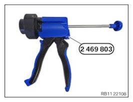
Brake cleaner 2.0 500 ml, Spray can 83192365214 20, Canister 83192365215 - Have the special tool 2 469 803
ready.NOTE: TECHNICAL INFORMATION
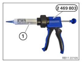
For additional information see: OVERVIEW OF CONSUMABLES (BMW PARTS CATALOGUE) - Position the sealing compound (1)
as shown on the special tool 2 469 803. SEALING COMPOUND DESCRIPTION
Loctite 5970 liquid sealing compound Processing time <10 minutes at room temperature 50 ml, Cartridge 83190404517 NOTE: TECHNICAL INFORMATION
The processing time of the liquid sealing compound can be at a maximum of 10 min.
Commissioning of the assembly is not possible until 25 minutes after the processing time.
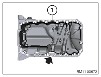
Non-observance can lead to leaks in the assembly. - Apply the sealing compound (1)
along the line with a height of 2 mm to 2.5 mm.NOTE: Apply the sealing compound along the inner edge.
- Completely encircle the oil return orifice (arrow) with the sealing compound.
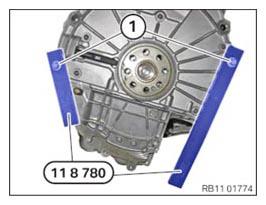
NOTE: TECHNICAL INFORMATION
The special tool 11 8 780 is only required when the transmission is removed. - Position the special tool 0 496 120 (11 8 780) with the transmission bolts (1) in such a way that the oil pan aligns exactly with the engine block.
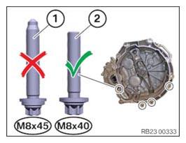
- If necessary, replace lining sleeves.NOTE: RISK OF DAMAGE
Improper screw length can cause component damage.
The use of screws of improper length can lead to component damage.- Note the correct screw length.
- Install screws that correspond to the original length.
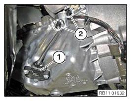
- Make sure that the correct
screw (2)
(M8x40) is used to attach the oil pan to the transmission.
The screw (1) (mounting bolt of the starter motor) must never be used to attach the oil pan.
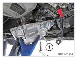
- Install the oil sump (1) towards the front and upwards.
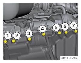
- Hand-tighten all screws of the oil pan, do not fully tighten them yet.
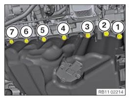
- Tighten the screws (1)
to (7)
.TIGHTENING TORQUES SPECIFICATION
Oil sump to crankcase M8x30 Tightening torque 24 Nm M8x110 Tightening torque 24 Nm - Tighten the screws (1)
to (7). TIGHTENING TORQUES SPECIFICATION
Oil sump to crankcase M8x30 Tightening torque 24 Nm M8x110 Tightening torque 24 Nm - Tighten the screws (1)
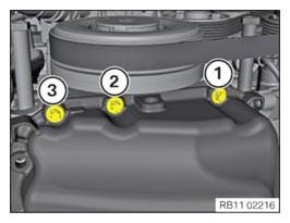
, (2)
and (3)
.TIGHTENING TORQUES SPECIFICATION
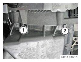
Oil sump to crankcase M8x30 Tightening torque 24 Nm M8x110 Tightening torque 24 Nm - Tighten down screws (1)
and (2)
.TIGHTENING TORQUES SPECIFICATION
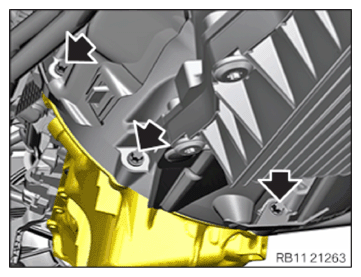
Oil sump to crankcase M8x30 Tightening torque 24 Nm M8x110 Tightening torque 24 Nm - Tighten the transmission bolts (arrows).TIGHTENING TORQUES SPECIFICATION
Transmission to oil pan (manual transmission and automatic transmission) M8x50 Tightening torque 19 Nm - Fasten cable on the clips (2) of the oil pan.
- Connect connectors (1) and lock.
- Make sure the connector (1)
engages audibly.