Removing all pistons with connecting rod
CAUTION:
Component with heavy weight.
Danger of injury!
Danger of injury!
- Note component's center of gravity.
- Support component using a jack.
- Secure component against falling off the jack.
CAUTION:
On releasing high pressure line, fuel may emerge at high speed.
Danger of injury!
Danger of injury!
- Wear suitable personal protective equipment.
- Allow the cooling system to cool down to a temperature below 40°C before starting installation work.
- Note warnings on cylinder head cover.
NOTE:
TECHNICAL INFORMATION
Collect and dispose of emerging fluids. Observe country-specific waste disposal regulations.
Collect and dispose of emerging fluids. Observe country-specific waste disposal regulations.
Preliminary works
- Refer to REMOVING ENGINE .
- Refer to INSTALLING THE ENGINE ON THE ASSEMBLY STAND
- Refer to RELEASING THE OIL DRAIN PLUG .
- Refer to TIGHTENING THE OIL DRAIN PLUG .
- Refer to REMOVING ALL SPARK PLUGS .
- Refer to REMOVE THE HIGH PRESSURE LINE BETWEEN THE HIGH PRESSURE PUMP AND THE RAIL .
- Refer to REMOVE HIGH PRESSURE PUMP .
- Refer to REMOVING THE RAIL WITH INJECTORS .
- Refer to REMOVING BOTH ACTUATORS .
- Refer to REMOVING THE CYLINDER HEAD COVER .
- Refer to REMOVE TANK VENT VALVE .
- Refer to REMOVING THE INTAKE PLENUM .
- Refer to REMOVE THE HEAT SHIELD AT THE CYLINDER HEAD
- Refer to REMOVING THE OIL RETURN LINE FOR THE EXHAUST TURBOCHARGER .
- Refer to REMOVE THE COOLANT RETURN LINE FOR THE EXHAUST TURBOCHARGER .
- Refer to REMOVE THE COOLANT FEED LINE FOR THE EXHAUST GAS TURBOCHARGER .
- Refer to BLOCKING ENGINE IN THE TDC FIRING POSITION .
- Refer to REMOVING CHAIN TENSIONER .
- Refer to RELEASING THE VANOS CENTRAL VALVE OF THE INTAKE ADJUSTER .
- Refer to RELEASING VANOS CENTRAL VALVE OF THE EXHAUST CAMSHAFT ADJUSTER .
- Refer to REMOVING THE VANOS CENTRAL VALVE OF THE INTAKE ADJUSTER .
- Refer to REMOVE THE VANOS CENTRAL VALVE OF THE EXHAUST CAMSHAFT ADJUSTER .
- Refer to REMOVING INTAKE ADJUSTER .
- Refer to REMOVE EXHAUST CAMSHAFT ADJUSTER .
- Refer to REMOVE THE TEST GAUGES TO FIX THE CAMSHAFTS .
- Refer to REMOVING THE CYLINDER HEAD .
- Refer to REMOVING THE CYLINDER HEAD GASKET .
- Refer to REMOVING THE ACOUSTIC COVER OF THE OIL SUMP .
- Refer to REMOVING FLYWHEEL .
- Refer to REMOVE FRONT AXLE DIFFERENTIAL .
- Refer to REMOVE BEARING SUPPORT .
- Refer to REMOVE OIL PAN
- Refer to REMOVE THE OIL VACUUM PUMP .
- Refer to REMOVING THE OIL DEFLECTOR
NOTE:
The description is for one component only. The procedure is identical for all further components.
Removing the piston with connecting rod
NOTE:
TECHNICAL INFORMATION
Piston, gudgeon pin, connecting rod and connecting rod bearing shells are matched to each other and balanced.
Always install the piston, gudgeon pin, connecting rod and connecting rod bearing shells in the cylinder from which they were removed.
Piston, gudgeon pin, connecting rod and connecting rod bearing shells are matched to each other and balanced.
Always install the piston, gudgeon pin, connecting rod and connecting rod bearing shells in the cylinder from which they were removed.
NOTE:
TECHNICAL INFORMATION
The connecting rods of the engine are balanced and are matched to each other.
A single connecting rod is not permitted to be replaced. Always replace all connecting rods.
The connecting rods of the engine are balanced and are matched to each other.
A single connecting rod is not permitted to be replaced. Always replace all connecting rods.
Detach the lower connecting rod bearing
NOTE:
RISK OF DAMAGE
Damage on the cylinder wall and oil spray nozzles.
Major force can scratch the cylinder wall and bend the oil spray nozzles.
Damage on the cylinder wall and oil spray nozzles.
Major force can scratch the cylinder wall and bend the oil spray nozzles.
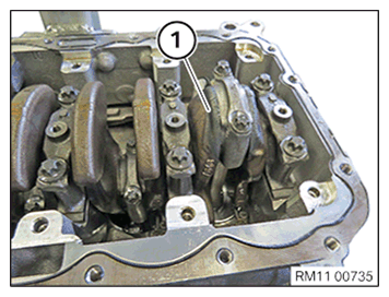
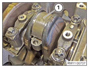
- Carefully move the piston and connecting rod in the engine block.
- Turn the crankshaft until the connecting rod bearing journal (1) reaches a vertical position.
NOTE:
RISK OF DAMAGE
Engine damage caused by incorrectly installed bearing shells and bearing supports.
Engine damage may result from incorrectly installing bearing shells and bearing supports.
Engine damage caused by incorrectly installed bearing shells and bearing supports.
Engine damage may result from incorrectly installing bearing shells and bearing supports.
- Always install all bearing shells and bearing supports in the same position from which they were removed.
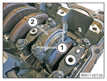
- Unscrew the connecting rod bolts (1).
- Remove the connecting rod bearing cap (2) and put to one side in the correct order.
Make sure that the connecting rod bearing cap (2) can be re-installed in the correct position.
NOTE:
RISK OF DAMAGE
Engine damage caused by incorrectly installed bearing shells and bearing supports.
Engine damage may result from incorrectly installing bearing shells and bearing supports.
Engine damage caused by incorrectly installed bearing shells and bearing supports.
Engine damage may result from incorrectly installing bearing shells and bearing supports.
- Always install all bearing shells and bearing supports in the same position from which they were removed.
- Remove the connecting rod bearing (1).
- Make sure that the connecting rod bearing (1) can be re-installed in the correct position.
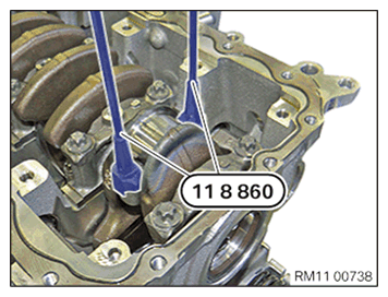
- Screw special tool 0 496 144 (11 8 860)
in at large connecting rod eye.
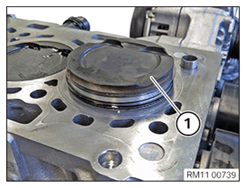
- Press piston (1) with connecting rod up and out of crankcase.