Removing the wiring harness of the engine transmission module for equipment specification without a gasoline particulate filter
NOTE:
RISK OF DAMAGE
Careless handling of tools and sharp-edged components.
Scratches, surface damage.
Careless handling of tools and sharp-edged components.
Scratches, surface damage.
- Protect working area.
- Handle tools and components carefully.
NOTE:
TECHNICAL INFORMATION
When the engine is stopped after the completion of trip, it may be necessary to run the electric fan. In rare cases, operation of the electric fan can last up to 11 min. This protects the components. In this case, replacing the electric fan will not remedy the problem!
When the engine is stopped after the completion of trip, it may be necessary to run the electric fan. In rare cases, operation of the electric fan can last up to 11 min. This protects the components. In this case, replacing the electric fan will not remedy the problem!
Preliminary work
- Refer to DISCONNECTING ALL BATTERY GROUND LEADS .
- Refer to REMOVING THE COVER PANEL OF THE LEFT DME CONTROL UNIT .
- Refer to REMOVING TOP CLEAN AIR PIPE .
- Refer to REMOVING THE CONTROL UNIT BRACKET FOR CYLINDERS 5 TO 8 .
- Refer to REMOVING COOLANT EXPANSION TANK .
- Refer to REMOVING THE COVER ON LEFT AND RIGHT IN THE ENGINE COMPARTMENT AT THE TOP .
- Refer to REMOVING THE LEFT AND RIGHT FRONT-END STRUT .
- Refer to REMOVING FRONT CROSS CONNECTION .
- Refer to REMOVING THE REAR TOP CROSS CONNECTION .
- Refer to REMOVING FAN COWL .
- Refer to REMOVING THE FRONT RIGHT LOWER WHEEL ARCH COVER .
- Refer to REMOVING THE LEFT FRONT BOTTOM WHEEL ARCH COVER .
- Refer to REMOVING THE FRONT UNDERBODY PROTECTION OR FRONT THRUST FIELD .
- Refer to REMOVING THE UNDERBODY PROTECTION OF THE STEERING GEAR AND THRUST FIELD RESPECTIVELY .
- Refer to DRAINING THE COOLANT FOR THE LOW-TEMPERATURE COOLANT CIRCUIT .
- Refer to REMOVING THE COOLANT EXPANSION TANK FOR THE LOW-TEMPERATURE COOLANT CIRCUIT (CHARGE AIR COOLER) .
- Refer to REMOVING LEFT CHARGE AIR COOLER .
- Refer to REMOVING LEFT THROTTLE VALVE ASSEMBLY .
- Refer to IF INSTALLED: REMOVE THE TORSION STRUT ON THE RIGHT AND LEFT WHERE REQUIRED .
- Refer to REMOVING THE CONNECTING SUPPORT FROM THE TUNNEL .
- Refer to REMOVING CENTER REAR UNDERSHIELD .
- Refer to REMOVING EXHAUST SYSTEM .
- Refer to REMOVING THE HEAT SHIELDS .
- Refer to COMPLETELY REMOVING THE PROP SHAFT (PLUG-IN - REAR FLEXIBLE DISC) .
- Refer to REMOVING THE HEAT SHIELD ON THE RIGHT TUNNEL .
- Refer to SLIGHTLY LOWER THE TRANSMISSION .
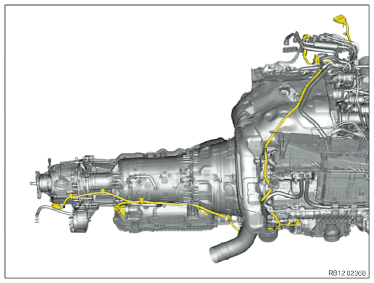
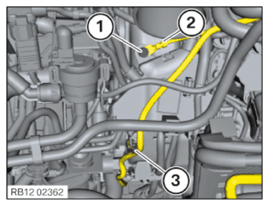
Overview graphic for the engine wiring harness, transmission module
- Disengage clip of the wiring harness (1) with conventional expanding rivet jack.
- Unlock and disconnect plug connections (2).
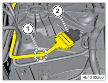
- Disengage clip of the wiring harness (1) with conventional expanding rivet jack.
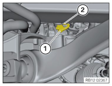
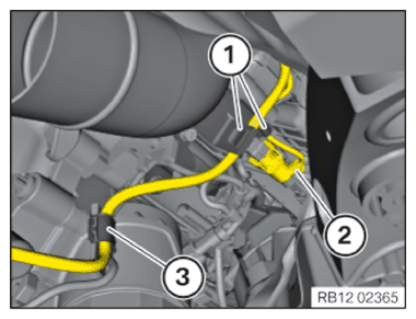
- Release the screw (1) on the grounding point (2).
- Release the retaining clip (3).
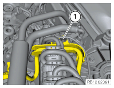
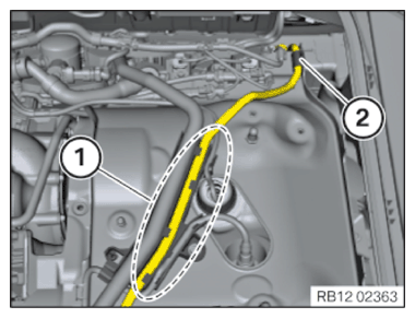
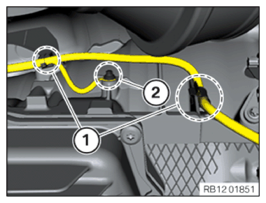
- Feed out the wiring harness in area (1).
- Unclip the wiring harness on the retaining clip (2).
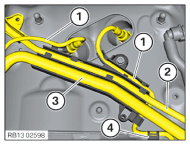
- Unclip the cable of the Lambda oxygen sensor (1)
- from the bracket.
- Unclip wiring harness (2).
- Unclip intake line (3).
- Unclip the cable of the Lambda oxygen sensor from the bracket (4).
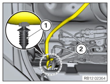
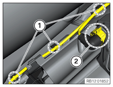
- Release the wiring harness in area (2) at the clips (1).
- Unlock plug connection (1) and disconnect.
- Release the wiring harness mounting (2).
- Unclip the wiring harness on the retaining clips (1) and (3).
- Unlock plug connection (2) and disconnect.
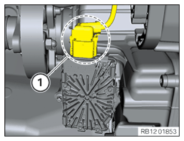
- Disengage latch mechanisms of the transmission wiring harness (1).
- Loosen screw (2).
- Disengage latch mechanisms of the transmission wiring harness (1).
- Turn connector with bayonet fitting (2) counterclockwise and disconnect.
- Unlock plug connection (1) and disconnect.
- Feed out the engine wiring harness of the transmission module.