Version with a gasoline particulate filter: Installing the engine wiring harness of the transmission module
Overview graphic for the engine wiring harness, transmission module with gasoline particulate filter
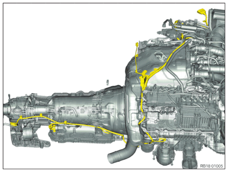
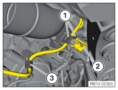
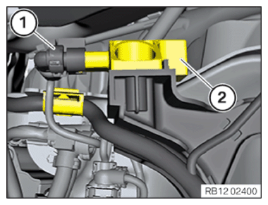
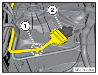
- Feed in the engine wiring harness of the transmission module.
- Connect connectors (1) and lock.
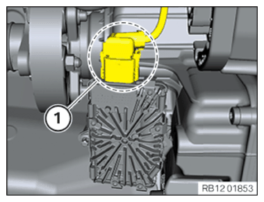
- Position the connector (2).
- Turn the connector with the bayonet closure (2) clockwise and lock.
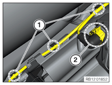
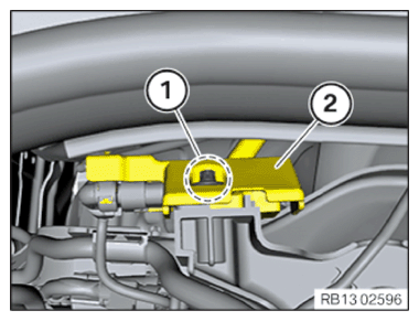
- Engage the detents (1) of the transmission wiring harness.
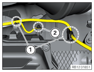
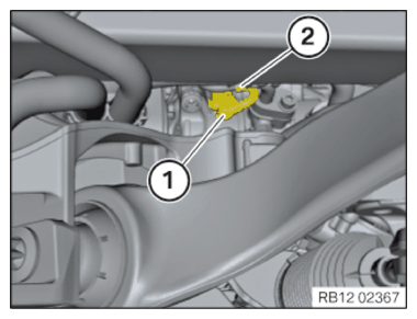
- Position the grounding point.
- Tighten down screw (2).
TIGHTENING TORQUES SPECIFICATION
| Ground connection on transmission | ||
| M6x12 screw | Tightening torque | 10 Nm |
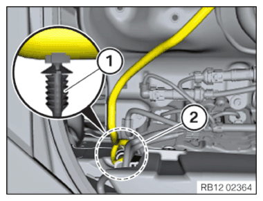
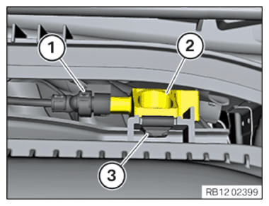
- Engage the detents (1) of the transmission wiring harness.
- Connect connectors (2) and lock.
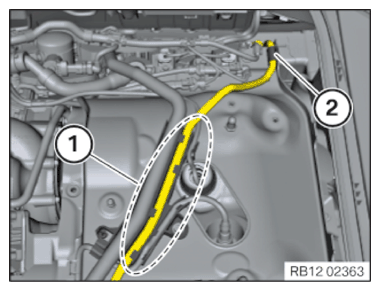
- Clip the wiring harness into the retaining clips (1) and (3).
- Secure the wiring harness mounting (2).
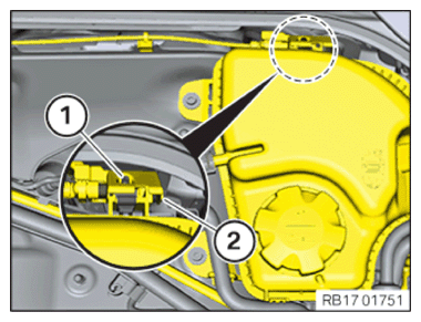
- Connect connectors (1) and lock.
- Secure the wiring harness in area (2) at the clips (1).
- Insert the wiring harness in area (1).
- Clip in the wiring harness at the retaining clip (2).
- Connect connectors (1) and lock.
- Position the gasoline particulate sensor (2).
- Position the holder (2) of the gasoline particulate sensor with the gasoline particulate sensor.
- Tighten down screw (1).
TIGHTENING TORQUES SPECIFICATION
| Gasoline particulate sensor to holder of cylinder bank 1 | ||
| Plastic screw 6x18 | Tightening torque | 5.5 Nm |
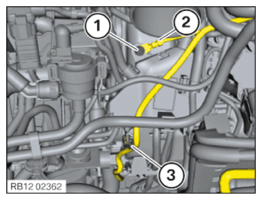
- Connect connectors (1) and lock.
- Position the clip nut (3).
- Position the gasoline particulate sensor (2).
- Position the holder (2) of the gasoline particulate sensor with the gasoline particulate sensor.
- Tighten down screw (1).
TIGHTENING TORQUES SPECIFICATION
| Gasoline particulate sensor to coolant expansion tank | ||
| M6x20 screw | Tightening torque | 8 Nm |
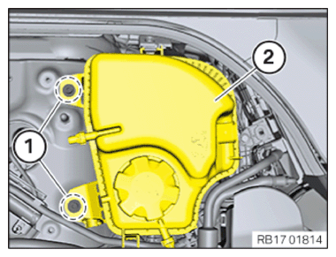
- Position the coolant expansion tank (2).
- Tighten the screws (1).
TIGHTENING TORQUES SPECIFICATION
| Coolant reservoir | ||
| M6x20 screw | Tightening torque | 11 Nm |
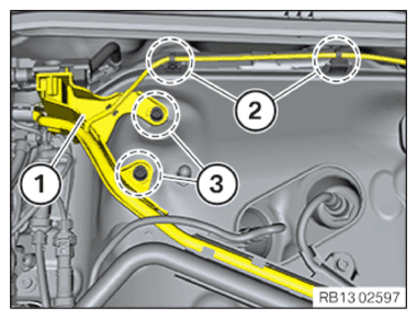
- Position the holder (1) of the gasoline particulate sensor.
- Tighten the screws (3).
TIGHTENING TORQUES SPECIFICATION
| Engine wiring harness of transmission module to holder for expansion tank | ||
| M6x16 screw | Tightening torque | 10 Nm |
- Fix wiring harness mountings (2).
- Position the grounding point (2).
- Tighten down screw (1).
TIGHTENING TORQUES SPECIFICATION
| Ground connection on cylinder head cover | ||
| M6x14 screw | Tightening torque | 10 Nm |
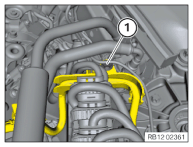
- Clip in the wiring harness at the retaining clip (3).
- Clip in the clips (1) of the wiring harness.
- Connect connectors (2) and lock.
- Clip in the clips (1) of the wiring harness.
Follow-up work
- Refer to FASTENING THE TRANSMISSION .
- Refer to INSTALLING THE HEAT SHIELD ON THE RIGHT TUNNEL .
- Refer to COMPLETELY INSTALLING THE PROP SHAFT (PLUG-IN - REAR FLEXIBLE DISC) .
- Refer to INSTALLING THE HEAT SHIELDS .
- Refer to INSTALLING EXHAUST SYSTEM .
- Refer to INSTALLING CENTER REAR UNDERSHIELD .
- Refer to INSTALLING THE CONNECTING SUPPORTS ON THE TUNNEL .
- Refer to INSTALLING THE LEFT THROTTLE BODY .
- Refer to INSTALLING THE LEFT-HAND CHARGE AIR COOLER .
- Refer to INSTALLING THE COOLANT EXPANSION TANK FOR THE LOW-TEMPERATURE COOLANT CIRCUIT (CHARGE AIR COOLER) .
- Refer to SEALING OFF COOLANT FOR LOW-TEMPERATURE COOLANT CIRCUIT .
- Refer to INSTALLING THE UNDERBODY PROTECTION OF THE STEERING GEAR OR THE FRONT THRUST FIELD .
- Refer to INSTALLING THE FRONT UNDERBODY PROTECTION OR FRONT THRUST FIELD .
- Refer to INSTALLING THE FRONT LEFT BOTTOM WHEEL ARCH COVER .
- Refer to INSTALLING THE FRONT BOTTOM RIGHT WHEEL ARCH COVER .
- Refer to INSTALLING FAN COWL .
- Refer to INSTALLING THE REAR TOP CROSS CONNECTION .
- Refer to INSTALLING FRONT CROSS CONNECTION .
- Refer to INSTALLING FRONT-END STRUT ON LEFT AND RIGHT .
- Refer to INSTALLING THE COVER ON THE LEFT AND RIGHT IN THE ENGINE COMPARTMENT AT THE TOP .
- Refer to FILLING THE LOW-TEMPERATURE COOLING SYSTEM WITH THE VACUUM FILLING EQUIPMENT .
- Refer to VENTING THE LOW-TEMPERATURE COOLING SYSTEM .
- Refer to INSTALLING COOLANT EXPANSION TANK .
- Refer to INSTALLING THE CONTROL UNIT BRACKET FOR CYLINDERS 5 TO 8 .
- Refer to INSTALLING CLEAN AIR PIPE, TOP .
- Refer to INSTALLING THE COVER OF THE LEFT DME CONTROL UNIT .
- Refer to CONNECTING NEGATIVE BATTERY CABLE .
- Refer to FILLING AND VENTING THE LOW-TEMPERATURE COOLANT CIRCUIT .