Installing the crankshaft
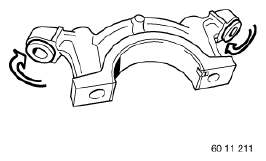
Rotate the threaded support sleeves in reverse
- Rotate the threaded support sleeves in the main bearing cap in reverse.
When replacing the crankshaft bearings or crankshaft
Replacement: Observing the classification of bearing shells
Engine damage caused by incorrectly installed bearing shells and bearing brackets.
If the bearing shells and bearing brackets are installed incorrectly, then engine damage can occur.
- Always install all bearing shells and bearing brackets in the same position from which they were removed.
The main bearing shells and guide bearing shells are classified by numbers.
Observe the classification of the main and guide bearing shells.
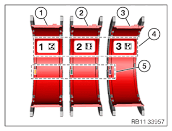
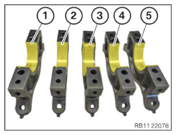
- Observe the classification of the bearing shells (1) through (3):
The bearing shell (1) has yellow color coding in the (5) area.
The bearing shell (2) has green color coding in the (5) area.
The bearing shell (3) has purple color coding in the (5) area.
- Make sure that the right classification is implemented in accordance with the (4) area.
- Replace the main bearing shells.
Parts : Main bearing shells
Observe the classification of the bearing shells.
The code letters of the crankshaft and crankcase mark the classification of the bearing shell for the respective bearing position.
The letters from the crankcase and crankshaft are required to determine the bearing shell colors.
The first letter from the left applies to the first bearing position on the timing chain drive system.
Bearing seat 3 is designed as a guide bearing.
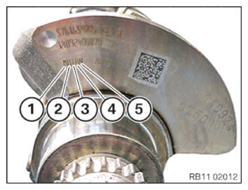
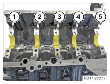
- Observe the assignment of classification of bearing seats (1) to (5) on the crankshaft:
| Bearing seats |
|---|
| Bearing seat 1 |
| Bearing seat 2 |
| Bearing seat 3 (guide bearing) |
| Bearing seat 4 |
| Bearing seat 5 |
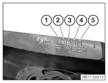
- Observe the assignment of classification of bearing seats (1) to (5) on the crankcase upper section:
| Bearing seats |
|---|
| Bearing seat 1 |
| Bearing seat 2 |
| Bearing seat 3 (guide bearing) |
| Bearing seat 4 |
| Bearing seat 5 |
Check
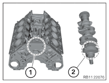
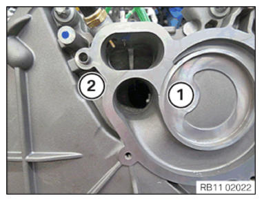
- Read the code letters and code numbers of crankcase (1) and crankshaft (2).
| Code letter on crankcase | Code numbers on the crankshaft | |
|---|---|---|
| Bearing seat 1 | ||
| Bearing seat 2 | ||
| Bearing seat 3 (guide bearing shells) | ||
| Bearing seat 4 | ||
| Bearing seat 5 |
Result
» Note the result in the table.
Measure
- Determine classification of the bearing shells based on further information: Table for bearing shells of bearing seat.
11 21 122 Table for bearing shells of bearing shells N63
- Insert the bearing shells in bearing seats (1), (2), (4) and (5).
- Insert bearing shell (3) in the guide bearing seat on the crankcase.
- Insert the bearing shells in bearing caps (1), (2), (4) and (5).
- Insert bearing shell (3) into the guide bearing cap.
- Install crankshaft.
- Position all main bearing caps with bearing shells.
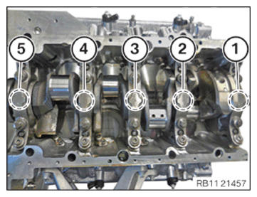
- Observe the assignment of the crankshaft bearing caps from (1) to (5).
- Replace screws.
Parts : Screws
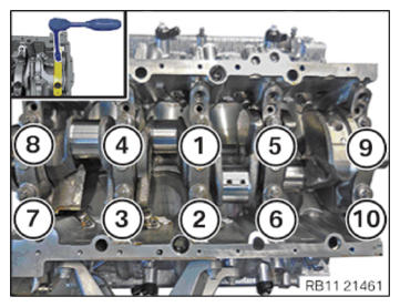
- Fasten the collar screws (M11) in the order (1) to (10).
| Bearing cap to crankcase (ASA (ASA) collar screw) | ||
|---|---|---|
| M11x99 Replace screws. Screw in hand-tight. |
Joining torque | 20 Nm |
| Angle of rotation | 125° | |
- Replace screws.
Parts : Screws
- Fasten the collar screws (M8) in the order (1) to (10).
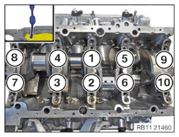
| Bearing cap to crankcase (ASA collar screw 10.9) | ||
|---|---|---|
| M8X70 Replace screw. |
Joining torque | 10 Nm |
| Angle of rotation | 63° | |
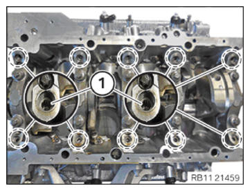
- Tighten all threaded support bushings (1).
| Threaded support bushing | ||
|---|---|---|
| Threaded support bushing |
Tightening torque | 6 Nm |
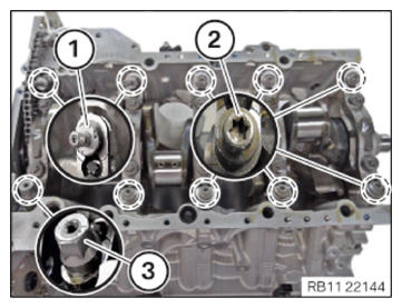
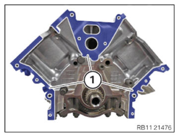
- Tighten the main bearing transverse screws on the spacer bolts (1), the screws (2), and the spacer screw (3).
| Angled screw connection to crankcase | ||
|---|---|---|
| M8x37 flat-head screw/spacer bolt/spacer screw | Joining torque | 10 Nm |
| Angle of rotation | 45° | |
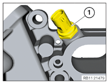
- Screw central bolt (1) into the crankshaft by hand.
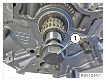
- Check the coefficient of friction at the crankshaft.
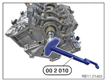
- Determine the crankshaft breakaway torque with the special tool 0 490 130 (00 2 010).
- Turn the crankshaft on the central bolt with the special tool.
| Crankshaft mounted | |
|---|---|
| Ease of movement of the crankshaft with connecting rod and piston | 0... 5 Nm |
- Correct the main bearing clearance in case the breakaway torque is too high.
- Unscrew the central bolt (1).
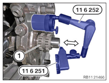
- Secure special tool with magnetic foot on crankcase.
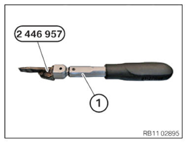
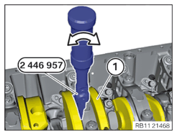
- Set the torque wrench (1) to 20 Nm.
- Attach the special tool 2 446 957 to the torque wrench.
- Set dial gauge to zero.
- Slide the crankshaft to the front in the arrow direction up to the stop at 20 Nm.
- Observe the deflection of the dial gauge.
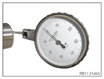
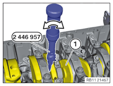
- Slide the crankshaft to the rear in the arrow direction up to the stop at 20 Nm.
- Observe the deflection of the dial gauge.
- Compare the side clearance of the crankshaft to the setpoint value and assess.
| Crankshaft bearing clearance, axial | |
|---|---|
| Crankshaft side clearance | 0.080... 0.246 mm |
- Remove the special tool.
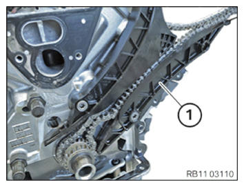
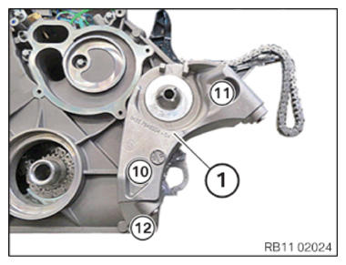
Install the tensioning rail of the timing chain for cylinder 5-8
- Position the tensioning rail (1) with the timing chain (2) on the gearing of the crankshaft.
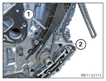
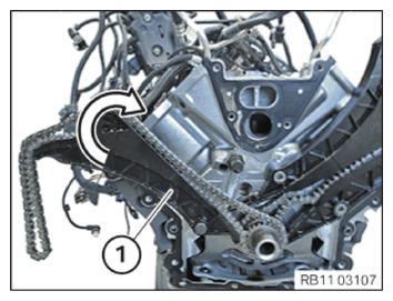
Install the guide rail of the timing chain for cylinders 5 to 8
- Attach and position the slide rail (1).
Install the tensioning rail of the timing chain for cylinder 1-4
- Position the tensioning rail (1) with timing chain on the gearing of the crankshaft.
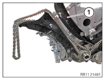
- Attach and position the slide rail (1).
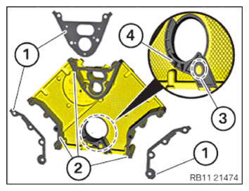
Mounting the beaded metal gaskets
- Clean sealing surfaces (2).
- Replacing the beaded metal gaskets (1).
- Securing the beaded metal gaskets (1) with the timing case cover screws.
- For timing case cover or timing chain replacement:
Loosen screw (3).
Remove jump guard (4).
Position jump guard (4).
Tighten down screw (3).
| Jump guard | ||
|---|---|---|
| M6x25 | Tightening torque | 10 Nm |
- For timing case cover or timing chain replacement:
Release and remount the coolant temperature sensor (1).
Tighten the coolant temperature sensor (1).
| Water/oil temperature sensor | ||
|---|---|---|
| Sensor M12x1.5 | Tightening torque | 18 Nm |
- The centering pins (1) must not be damaged, replace if necessary.
- Clean sealing surfaces (1).
Tightening the screw connection 1 on the front timing case cover
- Position the timing case cover.
- Tighten screws in the order (1) to (2).
Securing the screw connection 2 on the front timing case cover
- Tighten screws in the order (3) to (9).
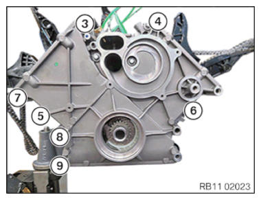
Mounting the screw connection 3 on the front timing case cover
- Position the carrier plate (1).
- Tighten screws in the order (10) to (12).
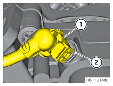
- Connect and lock the plug connection (1) to the coolant temperature sensor (2).
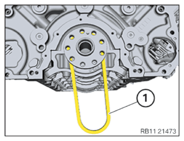
- Install the roller chain (1).
Installing the sealing cap with radial shaft seal (oil pan removed)
The sealing surfaces must be free of oil, grease and cleaning agents.
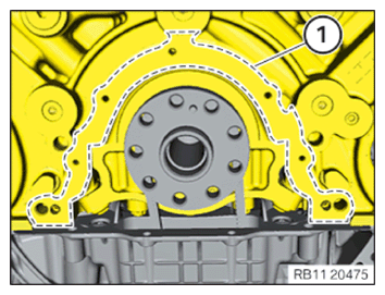
- Clean sealing surface (1).
- The sealing cap with radial shaft seal (1) must not be stored longer than 6 months without support bushing (2).
- The support bushing (2) must remain in the sealing cap with radial shaft seal (1) until installation as it is used as a slip bushing.
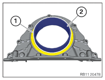
- Replace the sealing cap with radial shaft seal (1).
Parts : Sealing cap with radial shaft seal
- Coat the tire tread of the crankshaft with motor oil.
Engine oil
Technically suitable
engine oils for BMW
Group engines
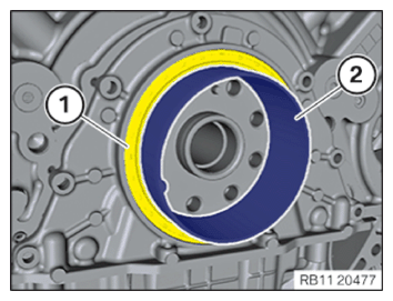
- Position and slide on the sealing cap with the radial shaft seal (1) and the support bushing (2) on the crankshaft.
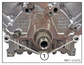
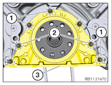
- Abut screws (1).
- Tighten down screws (2).
- Tighten down screws (1).
Follow-up work
- Refer to INSTALLING PISTON WITH CONNECTING ROD .
- Refer to INSTALLING UPPER OIL SUMP SECTION (ENGINE REMOVED) .
- Refer to INSTALLING THE OIL FILTER ELEMENT .
- Refer to INSTALL FRONT AXLE DIFFERENTIAL
- Refer to INSTALL OIL PUMP .
- Refer to INSTALL THE LOWER OIL PAN SECTION .
- Refer to INSTALLING THE RIGHT CYLINDER HEAD .
- Refer to INSTALLING BOTH RIGHT VANOS ADJUSTERS .
- Refer to REMOVING THE SPECIAL TOOL TO PRETENSION THE TIMING CHAIN AT CYLINDER BANK 1 .
- Refer to INSTALLING THE HYDRAULIC CHAIN TENSIONER OF CYLINDER BANK 1 .
- Refer to INSTALL THE SEALING CAP ON THE CYLINDER HEAD OF CYLINDER BANK 1 .
- Refer to INSTALLING THE CYLINDER HEAD COVER ON THE RIGHT .
- Refer to INSTALLING VANOS SOLENOID ACTUATOR, EXHAUST OF CYLINDER BANK 1 .
- Refer to INSTALL THE VANOS SOLENOID ACTUATOR INTAKE OF CYLINDER BANK 1 .
- Refer to INSTALLING RIGHT HIGH PRESSURE PUMP .
- Refer to INSTALLING THE INJECTORS FOR THE CYLINDERS 1 TO 4 .
- Refer to INSTALLING THE RIGHT HIGH-PRESSURE RAIL .
- Refer to INSTALL IGNITION COILS OF CYLINDER BANK 1 .
- Refer to PARTIALLY INSTALLING THE GUIDE TUBE FOR THE OIL DIPSTICK .
- Refer to INSTALLING THE LEFT CYLINDER HEAD .
- Refer to INSTALLING BOTH LEFT VANOS ADJUSTERS .
- Refer to REMOVING SPECIAL TOOL TO PRETENSION TIMING CHAIN ON CYLINDER BANK 2 .
- Refer to INSTALLING THE HYDRAULIC CHAIN TENSIONER OF CYLINDER BANK 2 .
- Refer to INSTALLING THE SEALING CAP ON THE CYLINDER HEAD OF CYLINDER BANK 2 .
- Refer to INSTALLING THE LEFT CYLINDER HEAD COVER .
- Refer to INSTALLING OIL FEED LINE ON EXHAUST TURBOCHARGER CYLINDERS 5 TO 8 .
- Refer to INSTALLING VANOS SOLENOID ACTUATOR, INTAKE OF CYLINDER BANK 2 .
- Refer to INSTALL THE VANOS SOLENOID ACTUATOR EXHAUST OF CYLINDER BANK 2 .
- Refer to INSTALL THE LEFT HIGH PRESSURE PUMP .
- Refer to INSTALLING FUEL DELIVERY LINE .
- Refer to INSTALL THE IGNITION COILS OF CYLINDER BANK 2 .
- Refer to INSTALLING BOTH EXHAUST TURBOCHARGERS .
- Refer to INSTALLING FUEL DELIVERY LINE .
- Refer to INSTALLING THE IGNITION COILS OF CYLINDERS 1 AND 5 .
- Refer to INSTALLING THE CLEAN AIR PIPE OF CYLINDER BANK 2 .
- Refer to INSTALLING CLEAN AIR PIPE OF CYLINDER BANK 1 .
- Refer to INSTALLING BOTH CHARGE AIR COOLERS .
- Refer to INSTALL THE COOLANT EXPANSION TANK FOR THE LOW-TEMPERATURE COOLANT CIRCUIT (CHARGE AIR COOLER) .
- Refer to CONNECTING THE LEFT CHARGE AIR LINE TO THE EXHAUST TURBOCHARGER .
- Refer to CONNECTING THE RIGHT CHARGE AIR LINE TO THE EXHAUST TURBOCHARGER .
- Refer to INSTALLING COOLANT PUMPS .
- Refer to INSTALLING THE VIBRATION DAMPER .
- Refer to INSTALLING THE BELT TENSIONER .
- Refer to INSTALL DRIVE BELT .
- Refer to INSTALLING THE FLYWHEEL .
- Refer to REMOVING THE ENGINE FROM THE ENGINE SUPPORT BRACKET .