Installing exhaust turbocharger
Further information is available.
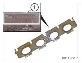
- Replace gasket.
Parts: Seals
- When installing the seal, make sure the part number (1) remains legible.
- Mount gasket (1).
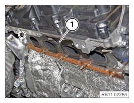
- Make sure the seal (1) is correctly installed on the guide pins.
- If necessary, have the seal (1) affixed by a support person.
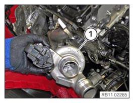
- Insert the exhaust turbocharger (1) and position it on the trim strip.
- Protect the exhaust turbocharger (1) from falling.
- Mount the reinforcement plate (1).
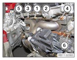
- Replace nuts (1) to (5).
Parts: Nuts
- Tighten the nuts in sequence (1) to (5).TIGHTENING TORQUES SPECIFICATION
Exhaust manifold to cylinder head Flange nut M7
Replace nuts.1. Joining torque 10 Nm 2. Joining torque 10 Nm 3. Joining torque 16 Nm 4. tightening torque 16 Nm - Check for correct installation of the seal on the guide pins between the exhaust manifold and the cylinder head.
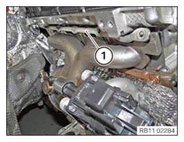
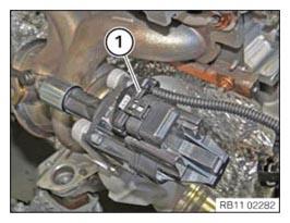
- If necessary, connect the connector (1) to the exhaust turbocharger and lock.
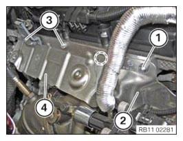
- Position the heat shield (4).
- Tighten down screws (3).TIGHTENING TORQUES SPECIFICATION
Heat shield to cylinder head M8 x 12 Tightening torque 19 Nm - Attach heat shield (2) in marked area.
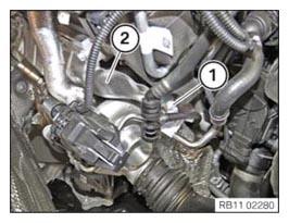
- Tighten down screw (1).TIGHTENING TORQUES SPECIFICATION
Heat shield to cylinder head M8 x 12 Tightening torque 19 Nm - Tighten the bolt (1) on the heat shield (2).TIGHTENING TORQUES SPECIFICATION
Heat shield to trim strip M6 x 12 Tightening torque 8 Nm
Follow-up work
- Refer to ATTACHING THE OIL RETURN LINE FOR THE EXHAUST TURBOCHARGER .
- Refer to INSTALLING THE OIL FEED LINE FOR THE EXHAUST TURBOCHARGER .
- Refer to INSTALLING THE COOLANT RETURN LINE FOR THE EXHAUST TURBOCHARGER .
- Refer to INSTALLING COOLANT FEED LINE FOR EXHAUST TURBOCHARGER .
- Refer to CONNECTING THE COOLANT LINE OF HIGH-TEMPERATURE COOLANT CIRCUIT .
- Refer to FILLING THE HIGH-TEMPERATURE COOLING SYSTEM WITH THE VACUUM FILLING EQUIPMENT .
- Refer to INSTALLING CATALYTIC CONVERTER .
- Refer to INSTALLING THE COMPLETE EXHAUST SYSTEM .
- Refer to INSTALLING THE REAR AXLE COVER .
- Refer to IF INSTALLED: INSTALL THE TORSION STRUT ON THE RIGHT, AND ON THE LEFT WHERE REQUIRED .
- Refer to INSTALLING THE CONNECTING SUPPORTS ON THE TUNNEL .
- Refer to INSTALLING THE OXYGEN SENSOR MONITOR .
- Refer to INSTALLING LAMBDA OXYGEN SENSOR .
- Refer to INSTALLING THE CYLINDER HEAD COVER ACOUSTIC COVER .
- Refer to INSTALLING CHARGE AIR LINE .
- Refer to INSTALLING CLEAN AIR PIPE .
- Refer to INSTALLING RESONATOR .
- Refer to INSTALLING ACOUSTIC COVER .
- Refer to INSTALLING THE REAR THRUST FIELD .
- Refer to INSTALLING THE UNDERBODY PROTECTION OF THE STEERING GEAR OR THE FRONT THRUST FIELD .
- Refer to INSTALLING THE FRONT UNDERBODY PROTECTION OR FRONT THRUST FIELD .
- Refer to VENTING THE HIGH-TEMPERATURE COOLANT SYSTEM .