Installing exhaust turbocharger
NOTE:
RISK OF DAMAGE
Damage of the electric wastegate valve controller.
Excessive force when removing and installing a jammed exhaust turbocharger may damage the electric wastegate valve controller.
Damage of the electric wastegate valve controller.
Excessive force when removing and installing a jammed exhaust turbocharger may damage the electric wastegate valve controller.
- Do not pull on the electric wastegate valve controller.
- Apply force only at the turbine housing and exhaust manifold.
- Do not pull on the compressor housing.
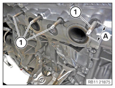
- Check screw-in depth (A) of upper stud bolts (1); if necessary, continue screwing in stud bolts or unscrew.TECHNICAL DATA - SCREW-IN DEPTH OF UPPER STUD BOLTS SPECIFICATION
Screw-in depth of upper stud bolts on cylinder head Dimension A
30 mmNOTE: RISK OF DAMAGE
Damage to the surface.
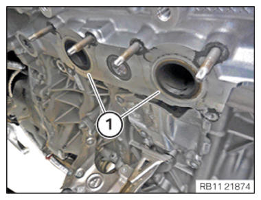
The use of metal-cutting tools (e.g., emery cloths) for cleaning surfaces can damage them and lead to leaks and/or engine damage.- Do not use any metal-cutting tools.
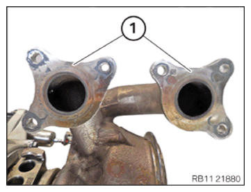
- Clean the sealing surfaces (1) on the cylinder head using special tool 0 495 102 (11 4 470).
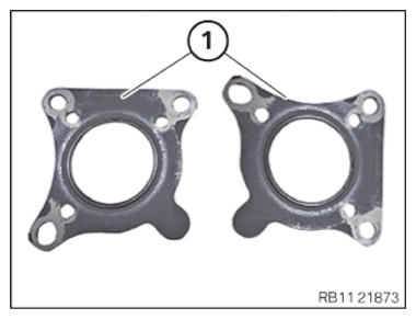
- Replace seals (1).
Parts: Gasket
- (1) Insert and install gaskets.
- Make sure the seals (1) are positioned correctly. NOTE: RISK OF DAMAGE
Damage to the surface.
The use of metal-cutting tools (e.g., emery cloths) for cleaning surfaces can damage them and lead to leaks and/or engine damage.- Do not use any metal-cutting tools.
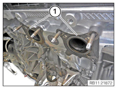
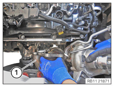
- Clean the sealing surfaces on the exhaust turbocharger (1) using special tool 0 495 102 (11 4 470). CAUTION: Heavy component.
Heavy components can lead to injury or damage.- Remove and install heavy components with the aid of another person/other persons.
- Insert and install the exhaust turbocharger (1).
- Protect the exhaust turbocharger (1) from falling.
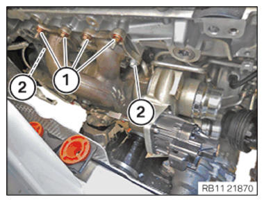
- Replace the nuts (1) and screws (2).
Parts: Nut and screws
- Insert the nuts (1) and screws (2).NOTE: Insert the screws in steps of 360 degrees.
- Tighten the nuts (1) and screws (2).TIGHTENING TORQUES SPECIFICATION
Exhaust turbocharger to cylinder head M7
Replace screws.
Replace nuts.1. Joining torque
2. tightening torque
3. tightening torque5 Nm
18 Nm
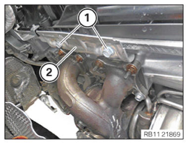
18 Nm - Feed in and install the heat shield (2).
- Replace screws (1).
Parts: screw
- Tighten down screws (1).TIGHTENING TORQUES SPECIFICATION
Heat shield of exhaust turbocharger to cylinder head top M8X12
Replace screws.tightening torque 19 Nm - Replace screw (1) and (2).
Parts: screw
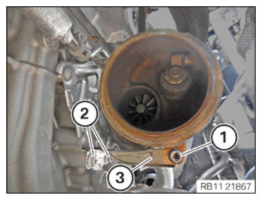
- Feed in the support (3) and position it.
- Tighten down screws (2).TIGHTENING TORQUES SPECIFICATION
Exhaust turbocharger support to crankcase M8x20
Replace screws.tightening torque 19 Nm
- Tighten down screw (1).TIGHTENING TORQUES SPECIFICATION
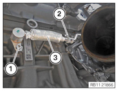
Exhaust turbocharger to support M8x25 Replace screw. tightening torque 19 Nm - Replace the sealing rings (1) on the coolant feed line (2) for the exhaust turbocharger with the special tool 0 496 714 (00 9 030).
Parts: Sealing rings
- Feed in and install the coolant feed line for the exhaust turbocharger (3).
- Tighten down screw (1).TIGHTENING TORQUES SPECIFICATION
Coolant feed line to crankcase M6X12 tightening torque 8 Nm - Tighten down screw (2).TIGHTENING TORQUES SPECIFICATION
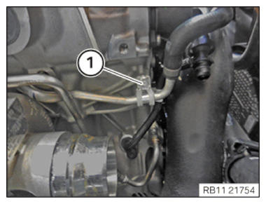
Coolant feed line to crankcase M6X12 tightening torque 8 Nm - Tighten down screw (1).TIGHTENING TORQUES SPECIFICATION
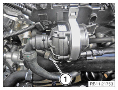
Coolant return line holder to crankcase M6X12 tightening torque 8 Nm - Connect and lock the coolant return line (1).
- Make sure that the coolant return line (1) engages audibly.
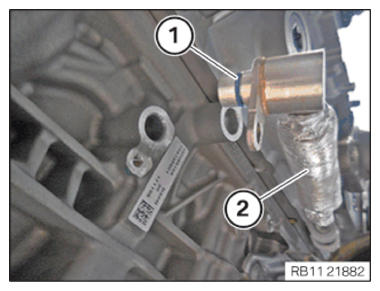
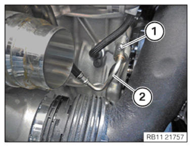
- Using the special tool 0 496 714 (00 9 030),
replace the sealing ring (2) on the oil feed line for the exhaust turbocharger.
Parts: Sealing rings
NOTE: TECHNICAL INFORMATION
Observe the sign in the engine compartment! Only fill with approved engine oil of the correct (Society of Automotive Engineers) vision grade. - Fill the oil feed line (2) for the exhaust turbocharger up to the edge with motor oil.
Engine oil
Technically suitable engine
oils for BMW Group
engines
- Insert and install the oil supply line (2).
- Tighten down screw (1).TIGHTENING TORQUES SPECIFICATION
Oil feed line for exhaust turbocharger to crankcase M6x12
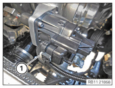
Replace sealing ring.tightening torque 8 Nm - Connect and lock the connector (1).
- Make sure the connector (1) engages audibly.
Follow-up work
- Refer to INSTALLING THE OIL RETURNING LINE FOR THE EXHAUST TURBOCHARGER .
- Refer to INSTALLING CATALYTIC CONVERTER .
- Refer to INSTALLING THE COMPLETE EXHAUST SYSTEM .
- Refer to INSTALLING THE CONNECTING SUPPORTS ON THE TUNNEL .
- Refer to IF INSTALLED: INSTALL THE TORSION STRUT ON THE RIGHT, AND ON THE LEFT WHERE REQUIRED .
- Refer to INSTALLING THE OXYGEN SENSOR MONITOR .
- Refer to INSTALLING LAMBDA OXYGEN SENSOR .
- Refer to INSTALL CHARGE AIR LINE .
- Refer to INSTALLING BOTTOM CLEAN AIR PIPE .
- Refer to INSTALLING THE RESONATOR WITH THE TOP CLEAN AIR PIPE .
- Refer to INSTALLING THE INTAKE FILTER HOUSING (TENSION STRUT REMOVED ON SHOCK TOWER) .
- Refer to INSTALLING FAN COWL .
- Refer to INSTALLING THE REAR TOP CROSS CONNECTION .
- Refer to INSTALLING FRONT CROSS CONNECTION .
- Refer to INSTALLING BOTH FRONT-END STRUTS .
- Refer to INSTALLING THE COVER ON THE LEFT AND RIGHT IN THE ENGINE COMPARTMENT AT THE TOP .
- Refer to FILLING AND VENTING THE HIGH-TEMPERATURE COOLANT CIRCUIT .
- Refer to CHECKING ENGINE OIL LEVEL .
- Refer to INSTALLING THE COVER OF THE STEERING ASSEMBLY .
- Refer to INSTALLING THE FRONT UNDERBODY PROTECTION OR FRONT THRUST FIELD .
- Refer to INSTALLING THE UNDERBODY PROTECTION OF THE STEERING GEAR OR THE FRONT THRUST FIELD .
- Refer to INSTALLING THE THRUST FIELD .
- Refer to INSTALLING REAR UNDERBODY PROTECTION .
- Refer to INSTALLING ACOUSTIC COVER .
- Refer to TAKING HOOD OUT OF THE SERVICE POSITION .