Remove front axle carrier
WARNING:
Car may slip off the vehicle hoist where components are supported.
Danger! Immobilization period-threatening injuries!
Danger! Immobilization period-threatening injuries!
- Secure the vehicle hoist against lowering and lifting.
WARNING:
Vehicle may slip off the vehicle hoist if the vehicle hoist is handled incorrectly.
Danger! Immobilization period-threatening injuries!
Danger! Immobilization period-threatening injuries!
- Observe safety instructions on raising the vehicle using a vehicle hoist.
- For additional information see: RAISING THE VEHICLE USING A VEHICLE LIFT .
WARNING:
Car may slip off the vehicle hoist if the weight is distributed unevenly.
Danger! Immobilization period-threatening injuries!
Danger! Immobilization period-threatening injuries!
- Ensure there is a specific weight compensation on the car.
NOTE:
TECHNICAL INFORMATION
Perform wheel alignment after installation.
Perform wheel alignment after installation.
Preliminary work
- Refer to BRINGING FRONT COMPARTMENT LID IN THE SERVICE POSITION .
- Refer to REMOVING THE COVER ON LEFT AND RIGHT IN THE ENGINE COMPARTMENT AT THE TOP .
- Refer to REMOVING THE COVER OF THE REAR RIGHT ENGINE COMPARTMENT .
- Refer to REMOVING THE COVER OF THE ENGINE COMPARTMENT AT THE REAR LEFT .
- Refer to REMOVING THE MOUNT OF THE HOOD SEAL .
- Refer to REMOVING THE LATERAL HOOD SEALS .
- Refer to REMOVING THE FRONT LEFT AND RIGHT WHEELS .
- Refer to REMOVING THE REAR SECTION OF THE WHEEL ARCH COVER ON THE FRONT LEFT AND RIGHT .
- Refer to MOVING THE ENGINE TO THE INSTALLATION POSITION .
- Refer to REMOVING THE FRONT UNDERBODY PROTECTION OR FRONT THRUST FIELD .
- Refer to REMOVING THE UNDERBODY PROTECTION OF THE STEERING GEAR AND THRUST FIELD RESPECTIVELY .
- Refer to REMOVING THE STIFFENING PLATE .
- Refer to IF INSTALLED: REMOVING THE SILENCER OF THE STATIONARY HEATING .
- Refer to REMOVING THE REINFORCEMENT STRUT FROM THE ENGINE MOUNT ON THE LEFT AND RIGHT .
- Refer to REMOVING LEFT AND RIGHT BRAKE VENTILATION DUCT .
- Refer to REMOVING THE WHEEL ARCH COVER ON THE FRONT LEFT AND BOTTOM RIGHT .
- Refer to REMOVING THE COVER OF THE STEERING ASSEMBLY ON THE LEFT AND RIGHT .
- Refer to DETACHING THE WIRING HARNESS OF THE EPS FROM THE FRONT AXLE SUPPORT .
- Refer to LOOSENING THE ANTI-ROLL BAR LINK ON THE LEFT AND RIGHT FROM THE ANTI-ROLL BAR .
- Refer to IF INSTALLED: REMOVING THE ANTI-ROLL BAR .
- Refer to IF INSTALLED: REMOVING THE ACTIVE STABILIZER .
- Refer to REMOVING THE UNIVERSAL JOINT ON THE STEERING GEAR .
- Refer to RELEASING THE TIE ROD ON THE LEFT AND RIGHT FROM THE SWIVEL BEARING .
- Refer to REMOVING THE STEERING GEAR .
- Refer to LOOSENING THE TENSION STRUT ON THE LEFT AND RIGHT FROM THE FRONT AXLE SUPPORT .
- Refer to RELEASING THE BOTTOM WISHBONE ON THE LEFT AND RIGHT FROM THE FRONT SUBFRAME .
- Refer to DETACHING COOLANT HOSES FROM THE FRONT AXLE SUPPORT .
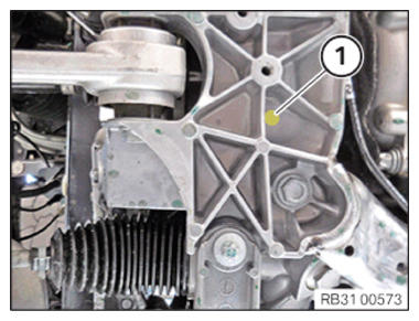
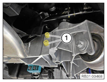
If installed on left: Remove spray guard
- Loosen screw (1) from spray guard.
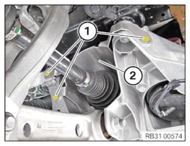
- Loosen screws (1) from spray guard (2).
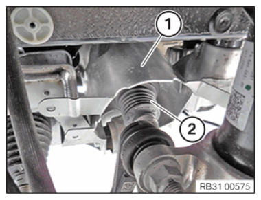
- Leave the spray guard (1) loose on output shaft (2).
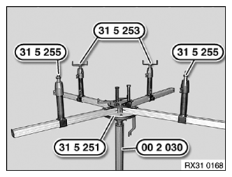
Preparing the special tool
NOTE: TECHNICAL INFORMATION
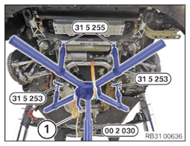
In a profile rail pair, two profile rails are connected to one another by gearing. - Position the special tool fully on special tool 0 490 133 (00 2 030) with the help of a support person.
- Insert special tools 0 495 821 (31 5 255) in telescopic supports of a profile rail pair.
- Insert special tools 0 495 819 (31 5 253)
in telescopic supports of other profile rail pair.
- Align special tools 0 495 819 (31 5 253) and 0 495 821 (31 5 255) to front axle support.
- Support the front axle support by operating the special tool (workshop jack) 0 490 133 (00 2 030).
- Secure the front axle using a luggage strap (1) on the special tool.
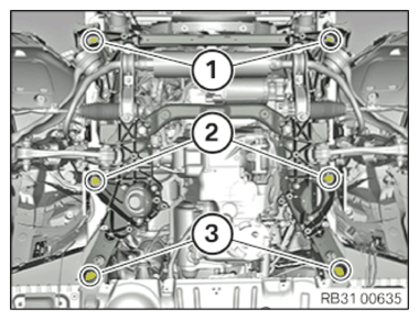
Unscrew the bolts on the front axle support
WARNING: Heavy component falling down or tipping.
Danger! Immobilization period-threatening injuries!- Before lowering or removing the front axle: Secure the engine in the INSTALLATION POSITION .
NOTE: Perform the steps on the right and left side. - Loosen screws (1).
- Loosen screws (1) to (3).
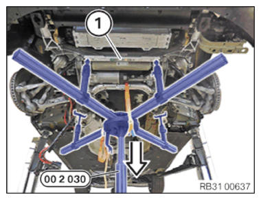
- Carefully lower the special tool 0 490 133 (00 2 030) and remove the front axle support (1).