Checking the timings of the camshaft
WARNING:
Hot surfaces.
Risk of burning!
Risk of burning!
- Perform all work only on components that have cooled down.
WARNING:
Working on fuel system.
Risk of fire! Danger of explosion!
Risk of fire! Danger of explosion!
- When working on the fuel system, make sure the workstation has sufficient ventilation, e.g., by means of extraction.
- Tightly seal off open lines and connections; collect any leakage fuel directly at the point of exit.
- No fire, sparks, open flames or smoking.
CAUTION:
On releasing high pressure line, fuel may emerge at high speed.
Injury hazard!
Injury hazard!
- Wear suitable personal protective equipment.
- Before performing any installation work, allow cooling system to cool down to less than 40°C.
- Note warnings on cylinder head cover.
NOTE:
TECHNICAL INFORMATION
Collect and dispose of emerging fluids. Observe country-specific waste disposal regulations.
Collect and dispose of emerging fluids. Observe country-specific waste disposal regulations.
Preliminary work
- Refer to BRINGING FRONT COMPARTMENT LID IN THE SERVICE POSITION .
- Refer to DISCONNECTING ALL BATTERY GROUND LEADS .
- Refer to REMOVING THE COVER OF THE ENGINE COMPARTMENT AT THE REAR LEFT .
- Refer to REMOVING THE COVER OF THE REAR RIGHT ENGINE COMPARTMENT .
- Refer to REMOVING LEFT AND RIGHT WIPER ARM .
- Refer to REMOVING THE COWL COVER .
- Refer to REMOVING TRAILING LINK AT SPRING BOLT .
- Refer to REMOVING THE COWL UPPER PART IN THE CENTER .
- Refer to REMOVING THE SEALING FRAME ON LEFT AND RIGHT .
- Refer to REMOVING THE CENTER BULKHEAD LOWER PART .
- Refer to REMOVING THE ACOUSTIC COVER .
- Refer to REMOVING THE SEAL FOR THE HOOD REAR .
- Refer to REMOVING ACOUSTIC COVER AT REAR .
- Refer to REMOVING RESONATOR .
- Refer to REMOVING THE ACOUSTIC COVER FOR THE ENGINE AT THE FRONT .
- Refer to REMOVING THE CYLINDER HEAD COVER ACOUSTIC COVER .
- Refer to n coils REMOVING THE IGNITION COIL .
- Refer to REMOVING ALL SPARK PLUGS .
- Refer to REMOVING THE HIGH PRESSURE LINE BETWEEN THE HIGH PRESSURE PUMP AND THE RAIL .
- Refer to REMOVING THE RAIL WITH INJECTORS .
- Refer to REMOVING FUEL DELIVERY LINE .
- Refer to REMOVING HIGH PRESSURE PUMP .
- Refer to REMOVING BOTH ACTUATORS .
- Refer to REMOVING THE CYLINDER HEAD COVER .
- Refer to REMOVING THE UNDERBODY PROTECTION OF THE STEERING GEAR AND THRUST FIELD RESPECTIVELY .
- Refer to REMOVING REAR UNDERBODY PROTECTION .
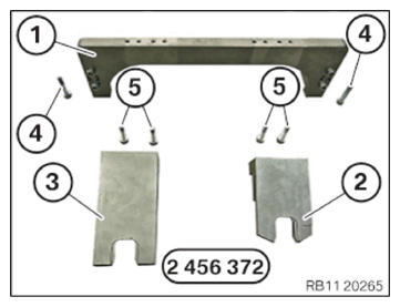
- Keep the set of special tools 2 456 372
at hand:
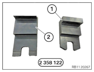
Number Description 1 Basic carrier 2 Setting gauge for adjusting the intake camshaft 3 Setting gauge for adjusting the exhaust camshaft 4 Screws of the basic carrier on the cylinder head 5 Screws of the gauge on the basic carrier - Refer to Check the test gauges from the set of special tools 2 358 122for completeness:
Number Description 1 Test gauges for fixing in place the intake camshaft 2 Test gauges for fixing in place the exhaust camshaft
NOTE:
RISK OF DAMAGE
Damage to the engine.
If the engine is manually rotated in the wrong direction of rotation, the engine can be damaged.
Damage to the engine.
If the engine is manually rotated in the wrong direction of rotation, the engine can be damaged.
- Only rotate the engine manually in the correct direction of rotation: a) clockwise when looking at the damper, or b) counterclockwise when looking at the chain drive, b) applies only if the timing chain is installed in the rear.
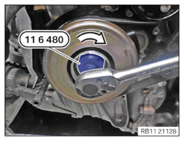
- With the special tool 0 493 380 (11 6 480) , turn the engine in arrow direction to the TDC firing position of cylinder 1 .
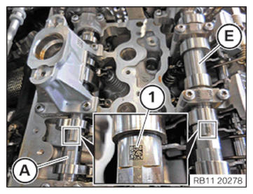
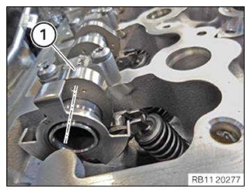
- Make sure the marks (1) on the intake camshaft (E) and the exhaust camshaft (A) are legible from above.
- Make sure the cam (1) on the exhaust camshaft on cylinder 1
is pointing slightly to the inside right at an angle.
- Make sure the cam (1) on the intake camshaft on cylinder 1
is pointing leftwards at an angle.
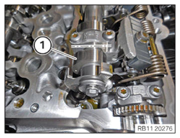
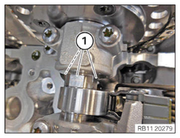
- Make sure that the flat sections (1) on the intake and exhaust camshafts point upwards.
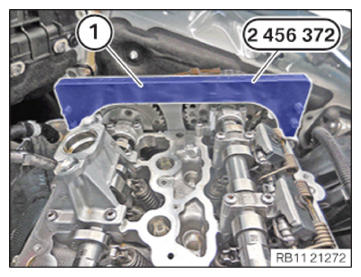
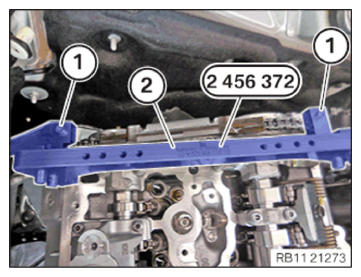
- Position the basic carrier (1) from the set of special tools 2 456 372
on the cylinder head.
- Refer to Tighten the screws (1) from special tool set 2 456 372on the basic carrier (2). TIGHTENING TORQUES SPECIFICATION
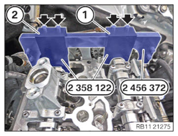
Basic carrier to cylinder head M6 Tightening torque 8 Nm - Position the test gauge (1) from the set of special tools 2 358 122 between the intake camshaft and the basic carrier from the set of special tools 2 456 372 .
- Position the test gauge (2) from the set of special tools 2 358 122 between the exhaust camshaft and the basic carrier from the set of special tools 2 456 372 .
- Tighten the screws (arrows).TIGHTENING TORQUES SPECIFICATION
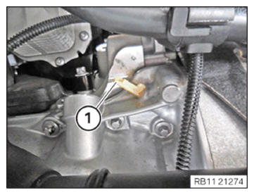
Test gauge to basic carrier M6 Tightening torque 8 Nm - Guide out and remove sealing cap (1).
- Vehicles with automatic transmission:
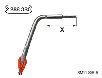
Dimension (X) = 66 mm
Special tool 2 288 380 must be inserted up to dimension (X) into the dowel hole.
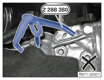
- Vehicles with automatic transmission:
Special tool 2 288 380 incorrectly positioned.
TDC firing position of cylinder 1 not achieved.
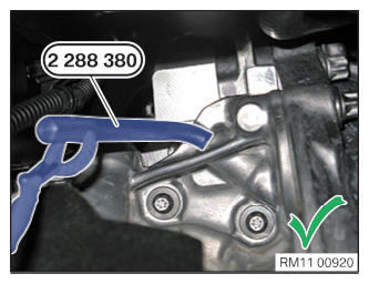
- Vehicles with automatic transmission:
Special tool 2 288 380 correctly positioned.
Engine is in TDC firing position of cylinder 1.
- Vehicles with manual gearbox:
Dimension (X) = 62 mm
Special tool 2 288 380 must be inserted up to dimension (X) into the dowel hole.
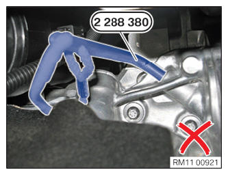
- Vehicles with manual gearbox:
Special tool 2 288 380 incorrectly positioned.
TDC firing position of cylinder 1 not achieved.
- Vehicles with manual gearbox:
Special tool 2 288 380 correctly positioned.
Engine is in TDC firing position of cylinder 1.
Follow-up work
- Refer to INSTALLING CYLINDER HEAD COVER .
- Refer to INSTALLING BOTH ACTUATORS .
- Refer to PREPARING THE INJECTORS FOR INSTALLATION .
- Refer to INSTALLING THE RAIL WITH INJECTORS .
- Refer to INSTALLING HIGH PRESSURE PUMP .
- Refer to INSTALLING THE HIGH-PRESSURE LINE BETWEEN THE HIGH-PRESSURE PUMP AND THE HIGH-PRESSURE RAIL .
- Refer to INSTALLING FUEL DELIVERY LINE .
- Refer to INSTALLING ALL SPARK PLUGS .
- Refer to INSTALLING IGNITION COIL .
- Refer to INSTALLING THE CYLINDER HEAD COVER ACOUSTIC COVER .
- Refer to INSTALLING THE ACOUSTIC COVER FOR THE ENGINE AT THE FRONT .
- Refer to INSTALLING RESONATOR .
- Refer to CONNECTING NEGATIVE BATTERY CABLE .
- Refer to INSTALLING CENTER BULKHEAD LOWER PART .
- Refer to INSTALLING THE SEALING FRAME ON LEFT AND RIGHT .
- Refer to INSTALLING ACOUSTIC COVER AT REAR .
- Refer to INSTALLING THE CENTER COWL UPPER PART .
- Refer to INSTALLING TENSION STRUT ON SHOCK TOWER .
- Refer to INSTALLING WINDSHIELD PANEL COVER .
- Refer to INSTALLING LEFT AND RIGHT WIPER ARM .
- Refer to INSTALLING THE REAR RIGHT ENGINE COMPARTMENT COVER .
- Refer to INSTALLING THE COVER OF THE ENGINE COMPARTMENT ON THE REAR LEFT .
- Refer to INSTALLING ACOUSTIC COVER .
- Refer to INSTALLING THE FRONT HOOD SEAL AT THE REAR .
- Refer to INSTALLING THE UNDERBODY PROTECTION OF THE STEERING GEAR OR THE FRONT THRUST FIELD .
- Refer to INSTALLING REAR UNDERBODY PROTECTION .
- Refer to TAKING HOOD OUT OF THE SERVICE POSITION .