Installing exhaust turbocharger
NOTE:
RISK OF DAMAGE
Damage of the electric wastegate valve controller.
Excessive force when removing and installing a jammed exhaust turbocharger may damage the electric wastegate valve controller.
Damage of the electric wastegate valve controller.
Excessive force when removing and installing a jammed exhaust turbocharger may damage the electric wastegate valve controller.
- Do not pull on the electric wastegate valve controller.
- Apply force only at the turbine housing and exhaust manifold.
- Do not pull on the compressor housing.
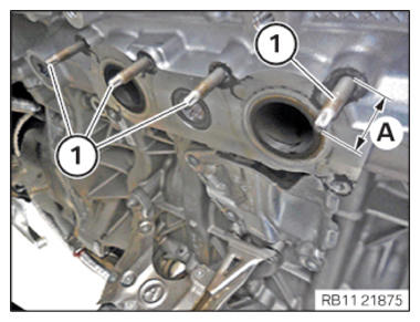
- Check screw-in depth (A) of upper stud bolts (1); if necessary, continue screwing in stud bolts or unscrew.TECHNICAL DATA - SCREW-IN DEPTH OF UPPER STUD BOLTS SPECIFICATION
Screw-in depth of upper stud bolts on cylinder head Dimension A 30 mm NOTE: RISK OF DAMAGE
Damage to the surface.
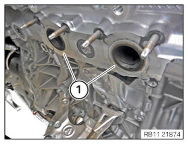
The use of metal-cutting tools (e.g., emery cloths) for cleaning surfaces can damage them and lead to leaks and/or engine damage.- Do not use any metal-cutting tools.
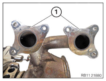
- Clean the sealing surfaces (1) on the cylinder head using special tool 0 495 102 (11 4 470)
.
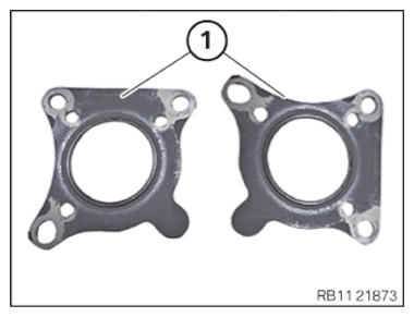
- Replace seals (1).
Parts: Gasket
- (1) Insert and install gaskets.
- Make sure the seals (1) are positioned correctly.NOTE: RISK OF DAMAGE
Damage to the surface.
The use of metal-cutting tools (e.g., emery cloths) for cleaning surfaces can damage them and lead to leaks and/or engine damage.- Do not use any metal-cutting tools.
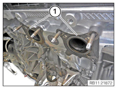
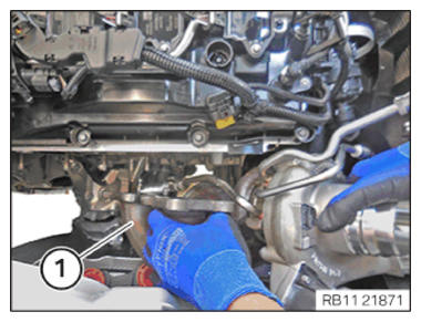
- Clean the sealing surfaces on the exhaust turbocharger (1) using special tool 0 495 102 (11 4 470)
.CAUTION: Heavy component.
Heavy components can lead to injury or damage.- Remove and install heavy components with the aid of another person/other persons.
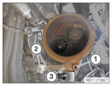
- Insert and install the exhaust turbocharger (1).
- Protect the exhaust turbocharger (1) from falling.
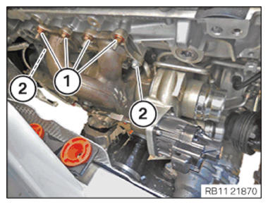
- Replace the nuts (1) and screws (2).
Parts: Nut and screws
- Insert the nuts (1) and screws (2).NOTE: Insert the screws in steps of 360 degrees.
- Tighten the nuts (1) and screws (2).TIGHTENING TORQUES SPECIFICATION
Exhaust turbocharger to cylinder head M7
Replace screws.
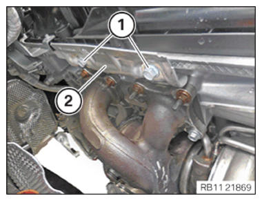
Replace nuts.1. Joining torque 5 Nm 2. tightening torque 18 Nm 3. tightening torque 18 Nm - Feed in and install the heat shield (2).
- Replace screws (1).
Parts: screw
- Tighten down screws (1).TIGHTENING TORQUES SPECIFICATION
Heat shield of exhaust turbocharger to cylinder head top M8X12
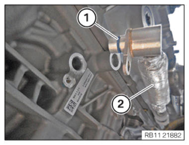
Replace screws.tightening torque 19 Nm - Replace screw (1) and (2).
Parts: screw
- Feed in the support (3) and position it.
- Tighten down screws (2).TIGHTENING TORQUES SPECIFICATION
Exhaust turbocharger support to crankcase M8 x 20
Replace screws.Tightening torque 19 Nm - Tighten down screw (1).TIGHTENING TORQUES SPECIFICATION
Exhaust turbocharger to support M8 x 25
Replace screw.Tightening torque 19 Nm - Replace the sealing rings (1) on the coolant feed line (2) for the exhaust turbocharger with the special tool 0 496 714 (00 9 030)
.
Parts: Sealing rings
- Feed in and install the coolant feed line for the exhaust turbocharger (3).
- Tighten down screw (1).TIGHTENING TORQUES SPECIFICATION
Coolant feed line to crankcase M6X12 tightening torque 8 Nm - Tighten down screw (2).TIGHTENING TORQUES SPECIFICATION
Coolant feed line to crankcase M6X12 tightening torque 8 Nm - Tighten down screw (1).TIGHTENING TORQUES SPECIFICATION
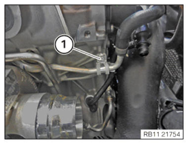
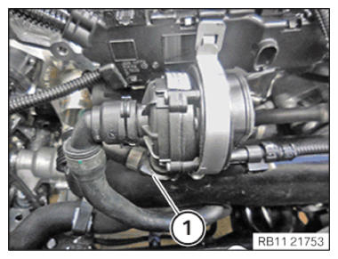
Coolant return line holder to crankcase M6X12 tightening torque 8 Nm - Connect and lock the coolant return line (1).
- Make sure that the coolant return line (1) engages audibly.
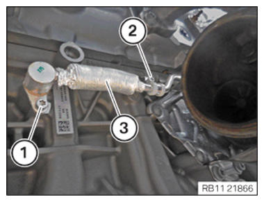
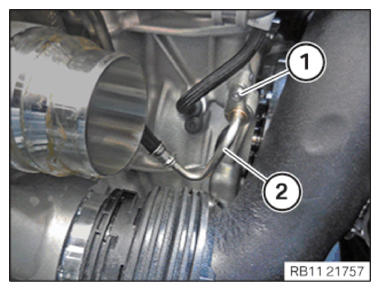
- Using the special tool 0 496 714 (00 9 030)
, replace the sealing ring (2) on the oil feed line for the exhaust turbocharger.
Parts: Sealing rings
NOTE: TECHNICAL INFORMATION
Observe the sign in the engine compartment! Only fill with approved engine oil of the correct (Society of Automotive Engineers) vise grade. - Fill the oil feed line (2) for the exhaust turbocharger up to the edge with motor oil.
Engine oil
Technically suitable engine
oils for BMW Group
engines
- Insert and install the oil supply line (2).
- Tighten down screw (1).TIGHTENING TORQUES SPECIFICATION
Oil feed line for exhaust turbocharger to crankcase M6 x 12
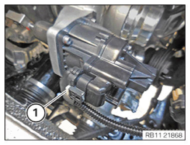
Replace sealing ring.tightening torque 8 Nm - Connect and lock the connector (1).
- Make sure the connector (1) engages audibly.
Follow-up work
- Refer to INSTALLING THE OIL RETURN LINE FOR THE EXHAUST TURBOCHARGER .
- Refer to INSTALLING CATALYTIC CONVERTER .
- Refer to INSTALLING THE COMPLETE EXHAUST SYSTEM .
- Refer to INSTALLING THE CONNECTING SUPPORTS ON THE TUNNEL .
- Refer to IF INSTALLED: INSTALL THE TORSION STRUT ON THE RIGHT, AND ON THE LEFT WHERE REQUIRED .
- Refer to INSTALLING THE OXYGEN SENSOR MONITOR .
- Refer to INSTALLING LAMBDA OXYGEN SENSOR .
- Refer to INSTALLING CHARGE AIR LINE .
- Refer to INSTALLING BOTTOM CLEAN AIR PIPE .
- Refer to INSTALLING THE RESONATOR WITH THE TOP CLEAN AIR PIPE .
- Refer to INSTALLING THE INTAKE FILTER HOUSING (TENSION STRUT REMOVED ON SHOCK TOWER) .
- Refer to INSTALLING FAN COWL .
- Refer to INSTALLING THE REAR TOP CROSS CONNECTION .
- Refer to INSTALLING FRONT CROSS CONNECTION .
- Refer to INSTALLING BOTH FRONT-END STRUTS .
- Refer to INSTALLING THE COVER ON THE LEFT AND RIGHT IN THE ENGINE COMPARTMENT AT THE TOP .
- Refer to FILLING AND VENTING THE HIGH-TEMPERATURE COOLANT CIRCUIT .
- Refer to CHECKING ENGINE OIL LEVEL .
- Refer to INSTALLING THE COVER OF THE STEERING ASSEMBLY .
- Refer to INSTALLING THE FRONT UNDERBODY PROTECTION OR FRONT THRUST FIELD .
- Refer to INSTALLING THE UNDERBODY PROTECTION OF THE STEERING GEAR OR THE FRONT THRUST FIELD .
- Refer to INSTALLING THE CENTER UNDERBODY PROTECTION .
- Refer to INSTALLING REAR UNDERBODY PROTECTION .
- Refer to INSTALLING ACOUSTIC COVER .
- Refer to TAKING HOOD OUT OF THE SERVICE POSITION .