Installing the component carrier
NOTE:
RISK OF DAMAGE
Damage to the surface.
The use of metal-cutting tools (e.g., emery cloths) for cleaning surfaces can damage them and lead to leaks and/or engine damage.
Damage to the surface.
The use of metal-cutting tools (e.g., emery cloths) for cleaning surfaces can damage them and lead to leaks and/or engine damage.
- Do not use any metal-cutting tools.
NOTE:
TECHNICAL INFORMATION
The sealing surfaces must be free of oil, grease and cleaning agents.
The sealing surfaces must be free of oil, grease and cleaning agents.
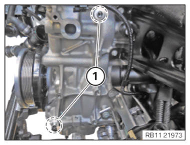
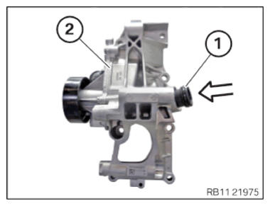
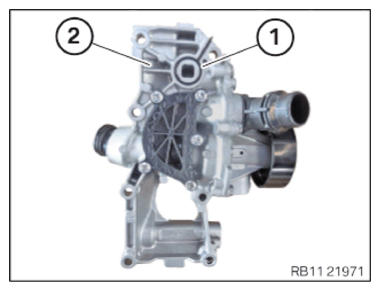
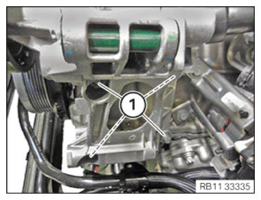
- Check centering sleeves (1) in the marked
areas for damage and, if necessary, replace them.
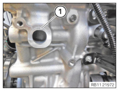
- Clean sealing surfaces (1) with special tool 0 495 102 (11 4 470)
.
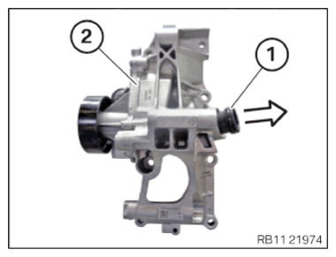
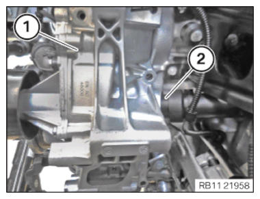
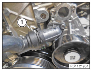
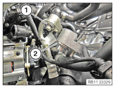
- Feed out and remove connecting pipe (1) from the function carrier (2) in direction of arrow.
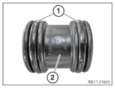
- Replace sealing rings (1) on thee connecting pipe (2).
- Parts: Sealing ring
- Coat sealing rings (1) with coolant before installing.
- Insert and install connecting pipe (1) on the function carrier (2) in the direction of arrow.
- Replace the sealing ring (1) on the component carrier (2).
Parts: Sealing ring
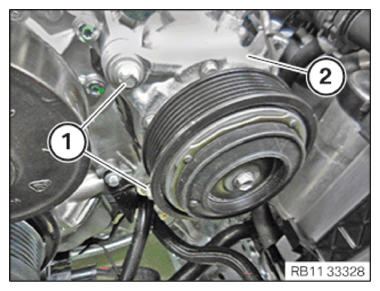
- Insert and install function carrier (1) using the connecting pipe (2).
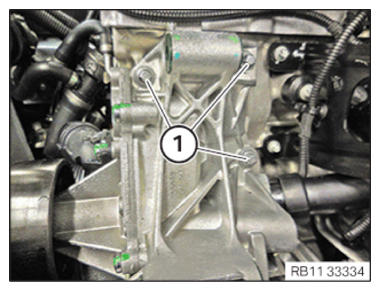
- Hand-tighten the bolts (1).
- Hand-tighten the bolts (1).
- Tighten down screws (1).TIGHTENING TORQUES SPECIFICATION
Coolant pump with function carrier on crankcase M8 x 35 tightening torque 19 Nm - Tighten down screws (1).TIGHTENING TORQUES SPECIFICATION
Coolant pump with function carrier on crankcase M8 x 35 tightening torque 19 Nm - Guide in and position the holder for the engine and the transmission oil lines.
- Tighten down screws (1).TIGHTENING TORQUES SPECIFICATION
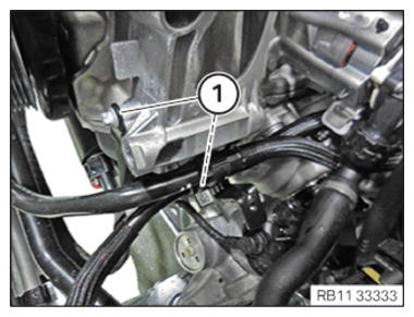
Engine holder - transmission oil line on the engine mount M6X16 tightening torque 12 Nm - Connect and lock coolant line (1).
- Make sure that the cooling line (1) engages audibly.
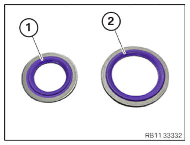
- Replace sealing rings (1) and (2).
Parts: Sealing ring
- Guide in and install sealing ring (1).
- Guide in and install sealing ring (2).
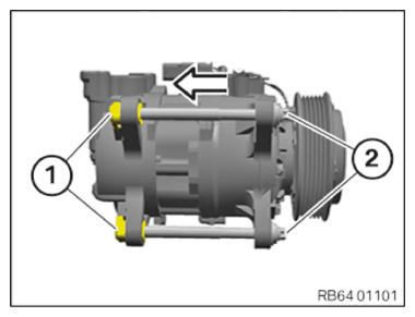
- Screw the screws (2) in the threaded support sleeves (1).
- Slightly press back the threaded support sleeves (1) with the help of screws (2) in the direction of arrow.
- Screw the screws (2) out of the threaded support sleeves (1) once again.
- Feed in the air conditioning compressor (2) and position it.
- Tighten the screws (1).TIGHTENING TORQUES SPECIFICATION
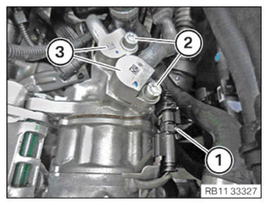
Air conditioning compressor in component carrier M10 Tightening torque 38 Nm - Feed in the refrigerant lines (3) and position them.
- Tighten the screws (2).TIGHTENING TORQUES SPECIFICATION
Refrigerant line on air conditioning compressor M8 tightening torque 19 Nm - Connect connectors (1) and lock.
The connector (1) must engage audibly.
Follow-up work
- Refer to INSTALLING THE COOLANT LINE BETWEEN THE CYLINDER HEAD AND THE COOLANT PUMP .
- Refer to INSTALLING THE STARTER MOTOR GENERATOR .
- Refer to INSTALLING THE DRIVE BELT FOR THE STARTER MOTOR GENERATOR .
- Refer to INSTALLING THE INTAKE PLENUM .
- Refer to INSTALLING THE TANK VENT VALVE .
- Refer to INSTALLING CHARGE AIR LINE .
- Refer to INSTALLING BOTTOM CLEAN AIR PIPE .
- Refer to INSTALLING CLEAN AIR PIPE, TOP .
- Refer to INSTALLING THE INTAKE FILTER HOUSING (TENSION STRUT REMOVED ON SHOCK TOWER) .
- Refer to INSTALLING FAN COWL .
- Refer to INSTALLING THE REAR TOP CROSS CONNECTION .
- Refer to INSTALLING FRONT CROSS CONNECTION .
- Refer to INSTALLING BOTH FRONT-END STRUTS
- Refer to INSTALLING THE COVER ON THE LEFT AND RIGHT IN THE ENGINE COMPARTMENT AT THE TOP
- Refer to INSTALLING THE CONTROL UNIT HOLDER .
- Refer to PARTIALLY INSTALLING THE INTEGRATED POWER SUPPLY MODULE (PDM) .
- Refer to INSTALLING THE DME CONTROL UNIT .
- Refer to EVACUATE AND CHARGE CONDITIONING .
- Refer to CONNECTING NEGATIVE BATTERY CABLE .
- Refer to ACTIVATING THE 48 V ELECTRICAL SYSTEM .
- Refer to FILLING AND VENT THE HIGH-TEMPERATURE COOLANT CIRCUIT .
- Refer to FILLING AND VENT THE LOW-TEMPERATURE COOLANT CIRCUIT .
- Refer to INSTALLING ACOUSTIC COVER AT REAR .
- Refer to INSTALLING THE FRONT HOOD SEAL AT THE REAR .
- Refer to INSTALLING ACOUSTIC COVER .
- Refer to INSTALLING THE UNDERBODY PROTECTION OF THE STEERING GEAR OR THE FRONT THRUST FIELD .
- Refer to INSTALLING THE FRONT UNDERBODY PROTECTION OR FRONT THRUST FIELD .
- Refer to TAKE HOOD OUT OF THE SERVICE POSITION .