Installing exhaust turbocharger
Further information is available.
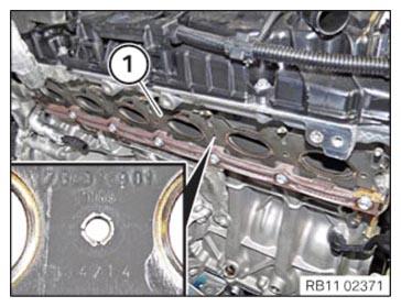
- Replace gasket (1).
Parts: Gasket
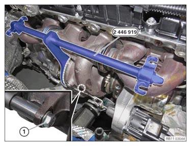
- Install seal (1) so that the part number is visible.NOTE: Do not damage the thermal compensating elements. Disassembly and installation including intermediate storage of the exhaust turbocharger is only permitted with mounted special tool 2 466 919.
- Thermal compensating element of the exhaust turbocharger/exhaust manifold should not be bent or deformed!
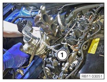
- Thread in exhaust turbocharger from top and position on the trim strip.
- Position the sliding rail (1).
- Install the sliding real (1) so that the part number is visible.
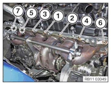
- Replace nuts (1) to (7).
Parts: Nuts
- Tighten nuts in the sequence (1) to (7) in semi-circular pattern.
TIGHTENING TORQUES SPECIFICATION
| Exhaust manifold to cylinder head | ||
| Flange nut M7 Replace flange nuts |
1. Joining torque | 10 Nm |
| 2. Tightening torque | 10 Nm | |
| 3. Joining torque | 16 Nm | |
| 4. Tightening torque | 16 Nm | |
| 5. Tightening torque | 16 Nm | |
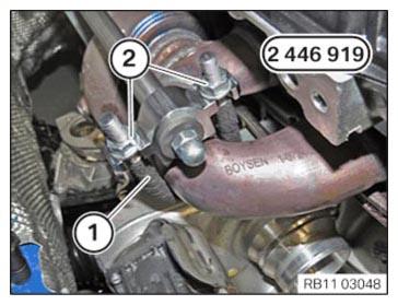
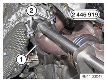
- Unscrew the nuts (2) and remove the retainer (1).
- Unscrew the nuts (2) and remove the retainer (1).
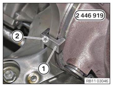
- Loosen screw (2) and remove holder (1).
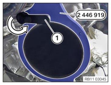
- Turn the clamping lever (1) against the direction of the arrow to release the special tool 2 446 919.
- Unscrew the bolt (1) and remove the special tool 2 446 919 from the exhaust turbocharger.
NOTE:
RISK OF DAMAGE
Dry running due to insufficient initial filling of the exhaust turbocharger.
Dry running due to insufficient initial filling of the exhaust turbocharger.
- Damage to the exhaust turbocharger.
- Be sure to do the initial filling when replacing the exhaust turbocharger.
- Fill the exhaust turbocharger with the matching additive (see applicable BMW parts catalogue).
- Fill the exhaust turbocharger additive (1) into the bores of the oil feed line.
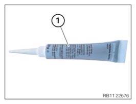
CONSUMABLE - EXHAUST TURBOCHARGER ADDITIVE DESCRIPTION
| Exhaust turbocharger additive, gasoline MSP | 17 ml, Tube | 83192457276 |
- Replace screws (2).
Parts: Screws
- Position support and tighten with the screw (2).
TIGHTENING TORQUES SPECIFICATION
| Exhaust turbocharger support to crankcase | ||
| M8 x 20 Replace screws. | tightening torque | 19 Nm |
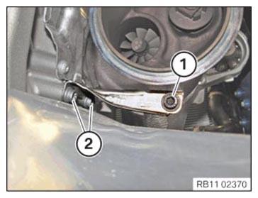
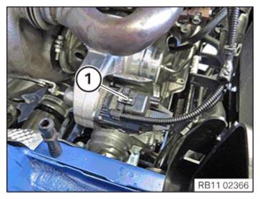
- Replace the screw (1).
Parts: Screw
- Tighten down screw (1).TIGHTENING TORQUES SPECIFICATION
Exhaust turbocharger to support M8 x 25 Replace screw. tightening torque 19 Nm - Replace O-ring.
Parts: O-ring
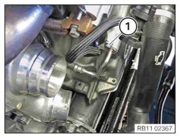
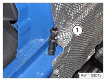
- Position oil feed line on engine block.
- Tighten down screw (1).
TIGHTENING TORQUES SPECIFICATION
| Oil feed line to crankcase | ||
| M6 x 12 | tightening torque | 8 Nm |
Follow-up work
- Refer to INSTALLING THE COOLANT FEED LINE (COOLANT RETURN LINE IS REMOVED) .
- Refer to INSTALLING HEAT SHIELD FOR CYLINDER HEAD COVER .
- Refer to INSTALLING THE FRONT SECTION OF THE COOLANT RETURN LINE .
- Refer to INSTALLING THE OIL RETURNING LINE FOR THE EXHAUST TURBOCHARGER .
- Refer to CONNECTING THE COOLANT LINES FOR THE HIGH-TEMPERATURE COOLANT CIRCUIT .
- Refer to FILLING THE HIGH-TEMPERATURE COOLING SYSTEM WITH THE VACUUM FILLING EQUIPMENT .
- Refer to INSTALLING CATALYTIC CONVERTER .
- Refer to REPLACING THE OXYGEN MONITOR SENSOR .
- Refer to INSTALLING LAMBDA OXYGEN SENSOR .
- Refer to INSTALLING CHARGE AIR LINE .
- Refer to INSTALLING BOTTOM CLEAN AIR PIPE .
- Refer to INSTALLING THE RESONATOR WITH THE TOP CLEAN AIR PIPE .
- Refer to INSTALLING INTAKE SILENCER HOUSING .
- Refer to INSTALLING FAN COWL .
- Refer to INSTALLING THE REAR TOP CROSS CONNECTION .
- Refer to INSTALLING FRONT CROSS CONNECTION .
- Refer to INSTALLING FRONT-END STRUT ON LEFT AND RIGHT .
- Refer to INSTALLING THE COVER ON THE LEFT AND RIGHT IN THE ENGINE COMPARTMENT AT THE TOP .
- Refer to INSTALLING ACOUSTIC COVER .
- Refer to PREPARING THE EXHAUST SYSTEM .
- Refer to INSTALLING THE COMPLETE EXHAUST SYSTEM .
- Refer to INSTALLING THE CONNECTING SUPPORTS ON THE TUNNEL .
- Refer to INSTALLING THE THRUST FIELD .
- Refer to INSTALLING FRONT STIFFENING PLATE .
- Refer to INSTALLING THE FRONT UNDERBODY PROTECTION OR FRONT THRUST FIELD .
- Refer to VENTING THE HIGH-TEMPERATURE COOLANT SYSTEM .