Install intake camshaft
- Clean all bearing positions and coat with motor oil.
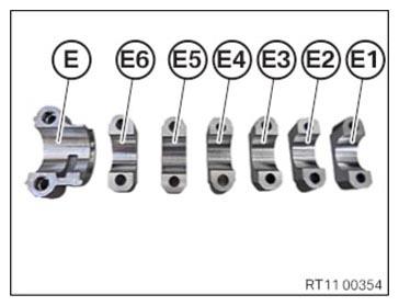
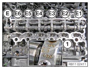
- Clean all bearing positions of intake camshaft bearing caps (E1) (E2) (E3), (E4) (E5) (E6) and (E) coat with motor oil.
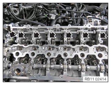
- Clean all bearing positions of the intake camshaft and coat with motor oil.
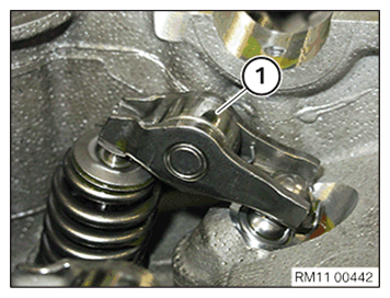
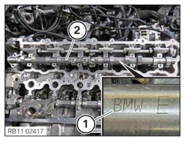
- Check all the roller cam followers (1) of the intake side for correct fit.
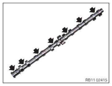
- Insert intake camshaft (2) in the bearing brackets in such a way that the mark (1) points towards the top.
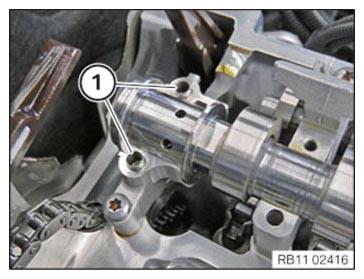
- Check fitting sleeves (1) of the thrust bearing for damage, replace if necessary.NOTE: RISK OF DAMAGE
Engine damage caused by incorrectly installed bearing shells and bearing brackets.
If the bearing shells and bearing brackets are installed incorrectly, then engine damage can occur.- Always install all bearing shells and bearing brackets in the same position from which they were removed.
- Coat all the intake camshaft bearing caps (E1) till (E6) and lay the bearing caps for the thrust bearing (E) with motor oil.
- Check the tensile strength of the screws for the bearing cap.
The illustration shows the screw with a tensile strength of 8.8.
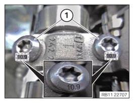
- Check the tensile strength of the screws for the bearing cap.
The illustration shows the screw with a tensile strength of 10.9.
NOTE: TECHNICAL INFORMATION
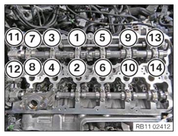
The camshaft is under tension due to the valve springs. Tighten or loosen each screw on the camshaft bearing caps in the prescribed sequence only by half a turn. Repeat procedure. - Press down the intake camshaft bearing cap and step-wise apply the screws in the order of (1) to (14) until hand-tight.
- Join all bolts in sequence (1) to (14) in half turns.
- Observe the joining torque.
- Tighten all screws in a sequence from (1) to (14).

TIGHTENING TORQUES SPECIFICATION
| Intake camshaft to cylinder head | ||
|---|---|---|
| M6 Tensile strength of screw 8.8 |
Joining torque | 9.6 Nm |
| tightening torque | 9.6 Nm | |
| M6 Tensile strength of screw 10.9 |
Joining torque | 11.8 Nm |
| tightening torque | 11.8 Nm | |
Follow-up work
- Refer to BLOCKING THE CAMSHAFTS .
- Refer to INSTALLING THE INTAKE ADJUSTER .
- Refer to PRELOAD TIMING CHAIN .
- Refer to TIGHTENING THE VANOS CENTRAL VALVE .
- Refer to CRANKING ENGINE TWICE (AUTOMATIC TRANSMISSION) .
- Refer to DISASSEMBLING ALL SPECIAL TOOLS .
- Refer to CHECKING INSTALLATION POSITION OF ROLLER CAM FOLLOWERS .
- Refer to CHECKING THE INTERMEDIATE LEVER CLASSIFICATION .
- Refer to INSTALLING ALL INTERMEDIATE LEVERS .
- Refer to INSTALLING ALL GATES .
- Refer to CHECKING THE POSITION OF THE INTAKE CAMSHAFT .
- Refer to CHECKING THE POSITION OF THE INTAKE CAMSHAFT AT CYLINDER 3 AND 4 .
- Refer to INSTALLING TORSION SPRINGS .
- Refer to INSTALLING CYLINDER HEAD COVER .
- Refer to INSTALLING BOTH ACTUATORS .
- Refer to PREPARING THE INJECTORS FOR INSTALLATION .
- Refer to INSTALLING THE INJECTORS FOR THE CYLINDERS 4 TO 6 .
- Refer to INSTALLING THE INJECTORS FOR THE CYLINDERS 1 TO 3 .
- Refer to PREPARING FOR THE INSTALLATION OF THE HIGH PRESSURE PUMP .
- Refer to INSTALLING HIGH PRESSURE PUMP .
- Refer to INSTALLING THE HIGH-PRESSURE LINE BETWEEN THE HIGH-PRESSURE RAIL AND THE HIGH-PRESSURE PUMP .
- Refer to INSTALLING FUEL DELIVERY LINE .
- Refer to REPLACING SPARK PLUGS .
- Refer to INSTALLING THE IGNITION COILS .
- Refer to INSTALLING THE INTAKE PLENUM .
- Refer to FASTENING CHARGE AIR LINE TO THE THROTTLE BODY .
- Refer to INSTALLING THE TANK VENT VALVE .
- Refer to INSTALLING CONTROL UNIT BRACKET .
- Refer to INSTALLING THE INTEGRATED POWER SUPPLY MODULE (PDM) .
- Refer to INSTALLING THE DME CONTROL UNIT .
- Refer to INSTALLING FRONT ENGINE ENCAPSULATION .
- Refer to CONNECTING THE COOLANT LINES FOR THE LOW-TEMPERATURE COOLANT CIRCUIT .
- Refer to INSTALLING FAN COWL .
- Refer to INSTALLING THE REAR TOP CROSS CONNECTION .
- Refer to INSTALLING FRONT CROSS CONNECTION .
- Refer to INSTALLING FRONT-END STRUT ON LEFT AND RIGHT .
- Refer to INSTALLING THE COVER ON THE LEFT AND RIGHT IN THE ENGINE COMPARTMENT AT THE TOP .
- Refer to INSTALLING THE RESONATOR WITH THE TOP CLEAN AIR PIPE .
- Refer to INSTALLING INTAKE SILENCER HOUSING .
- Refer to INSTALLING CENTER BULKHEAD LOWER PART .
- Refer to INSTALLING THE SEALING FRAME ON LEFT AND RIGHT .
- Refer to INSTALLING ACOUSTIC COVER AT REAR .
- Refer to INSTALLING THE CENTER COWL UPPER PART .
- Refer to INSTALLING TENSION STRUT ON SHOCK TOWER .
- Refer to INSTALLING WINDSHIELD PANEL COVER .
- Refer to INSTALLING LEFT AND RIGHT WIPER ARM .
- Refer to INSTALLING THE COVER OF THE ENGINE COMPARTMENT ON THE REAR LEFT .
- Refer to INSTALLING THE FRONT HOOD SEAL AT THE REAR .
- Refer to INSTALLING STARTER MOTOR .
- Refer to FILLING THE LOW-TEMPERATURE COOLING SYSTEM WITH THE VACUUM FILLING EQUIPMENT .
- Refer to CONNECTING NEGATIVE BATTERY CABLE .
- Refer to CONNECTING THE DIAGNOSTIC SYSTEM FOR POSSIBLE INTEGRATION LEVEL ENCODING AND PROGRAMMING .
- Refer to VENTING THE LOW-TEMPERATURE COOLING SYSTEM .
- Refer to INSTALLING THE THRUST FIELD .
- Refer to INSTALLING THE FRONT UNDERBODY PROTECTION OR FRONT THRUST FIELD .
- Refer to INSTALLING ACOUSTIC COVER .
- Refer to TAKING HOOD OUT OF THE SERVICE POSITION .
- Refer to CHECKING ENGINE OIL LEVEL .