Remove exhaust camshaft
WARNING:
High-voltage system.
The high-voltage system operates on the basis of hazardous, electrical voltage and high currents. Mortal hazard through electric shock!
The high-voltage system operates on the basis of hazardous, electrical voltage and high currents. Mortal hazard through electric shock!
- All work on the high-voltage system may only be carried out by specially trained and technically experienced personnel.
- For additional information see:
- For additional information see:
WARNING:
Hot surfaces.
Risk of burning!
Risk of burning!
- Perform all work only on components that have cooled down.
WARNING:
Working on fuel system.
Risk of fire! Danger of explosion!
Risk of fire! Danger of explosion!
- When working on the fuel system, make sure the workstation has sufficient ventilation, e.g., by means of extraction.
- Tightly seal off open lines and connections; collect any leakage fuel directly at the point of exit.
- No fire, sparks, open flames or smoking.
CAUTION:
On releasing high pressure line, fuel may emerge at high speed.
Injury hazard!
Injury hazard!
- Wear suitable personal protective equipment.
- Before performing any installation work, allow cooling system to cool down to less than 40°C.
- Note warnings on cylinder head cover.
NOTE:
TECHNICAL INFORMATION
Collect and dispose of emerging fluids. Observe country-specific waste disposal regulations.
Collect and dispose of emerging fluids. Observe country-specific waste disposal regulations.
Preliminary work
- Refer to DISCONNECTING ALL BATTERY GROUND LEADS .
- Refer to BRINGING FRONT COMPARTMENT LID IN THE SERVICE POSITION .
- Refer to REMOVING THE SEAL FOR THE HOOD REAR .
- Refer to REMOVING THE ACOUSTIC COVER .
- Refer to REMOVING THE COVER OF THE ENGINE COMPARTMENT AT THE REAR LEFT .
- Refer to REMOVING THE COVER OF THE REAR RIGHT ENGINE COMPARTMENT .
- Refer to REMOVING LEFT AND RIGHT WIPER ARM .
- Refer to REMOVING THE COWL COVER .
- Refer to REMOVING TRAILING LINK AT SPRING BOLT .
- Refer to REMOVING THE CENTER COWL UPPER PART .
- Refer to LOOSENING HIGH-VOLTAGE CABLES ON THE ELECTRICAL MACHINE ELECTRONICS .
- Refer to REMOVING ACOUSTIC COVER AT REAR .
- Refer to REMOVING LEFT SEALING FRAME .
- Refer to REMOVING THE CENTER BULKHEAD LOWER PART .
- Refer to REMOVING RESONATOR .
- Refer to REMOVING CHARGE AIR LINE .
- Refer to REMOVING THE ACOUSTIC COVER FOR THE ENGINE AT THE FRONT .
- Refer to REMOVING THE CYLINDER HEAD COVER ACOUSTIC COVER .
- Refer to REMOVING ALL IGNITION COILS .
- Refer to REMOVING ALL SPARK PLUGS .
- Refer to REMOVING THE HIGH PRESSURE LINE BETWEEN THE HIGH PRESSURE PUMP AND THE RAIL .
- Refer to REMOVING FUEL DELIVERY LINE .
- Refer to REMOVING THE RAIL WITH INJECTORS .
- Refer to REMOVING HIGH PRESSURE PUMP .
- Refer to REMOVING THE HOLDER OF THE POSITIVE BATTERY CABLE .
- Refer to REMOVING THE HEAT SHIELD AT THE CYLINDER HEAD .
- Refer to REMOVING BOTH ACTUATORS .
- Refer to REMOVING THE CYLINDER HEAD COVER .
- Refer to REMOVING THE FRONT UNDERBODY PROTECTION OR FRONT THRUST FIELD .
- Refer to REMOVING THE UNDERBODY PROTECTION OF THE STEERING GEAR AND THRUST FIELD RESPECTIVELY .
- Refer to REMOVING REAR THRUST FIELD .
- Refer to REMOVING REAR UNDERBODY PROTECTION .
- Refer to REMOVING THE THERMOSTAT FROM THE TRANSMISSION OIL LINES .
- Refer to REMOVING THE HOLDER FOR THE THERMOSTAT ON THE TRANSMISSION OIL LINE .
- Refer to BLOCKING ENGINE IN TDC FIRING POSITION .
- Refer to REMOVING CHAIN TENSIONER .
- Refer to RELEASING VANOS CENTRAL VALVE OF THE EXHAUST CAMSHAFT ADJUSTER .
- Refer to REMOVING THE VANOS CENTRAL VALVE OF THE EXHAUST CAMSHAFT ADJUSTER .
- Refer to REMOVING EXHAUST CAMSHAFT ADJUSTER .
- Refer to REMOVING THE TEST GAUGES FOR SECURING THE CAMSHAFTS .
NOTE:
RISK OF DAMAGE
Contaminant or foreign body.
Contamination can result in malfunctions, loss of function or leaks.
Contaminant or foreign body.
Contamination can result in malfunctions, loss of function or leaks.
- Adhere to the utmost cleanliness.
- Protect components from contamination e.g. by covering.
- Close off line connections with seal plugs.
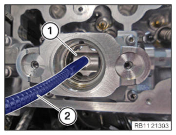
- Remove the roller tappet (1) using standard tools (2).
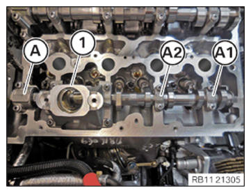
- Make sure the exhaust camshaft bearing cap (A1) (A2) and (A) is stored in the correct position 0 495 105 (11 4 480) in the special tool.NOTE: The exhaust camshaft bearing caps are legibly labeled from the intake side and marked with A1, A2 and A.NOTE: Exhaust camshaft bearing cap A is a thrust bearing.NOTE: Bearing cap 1 is the high pressure pump bracket.
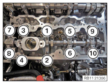
- Loosen all screws on the exhaust camshaft bearing cap in sequence from (10) to (1) in half turn.
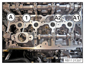
- Remove exhaust camshaft bearing caps (A1) (A2) and (A) and place in an ordered way in special tool 0 495 105 (11 4 480).
- Remove the high pressure pump bracket (1) and place it arranged in order in the special tool 0 495 105 (11 4 480).
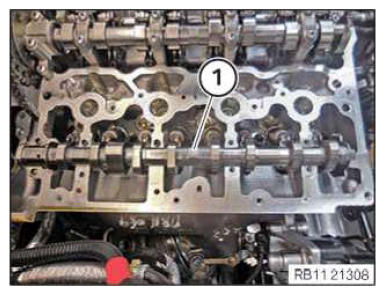
- Feed out and remove the exhaust camshaft (1).