Install exhaust camshaft
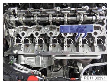
- Clean all the bearing positions (arrows).
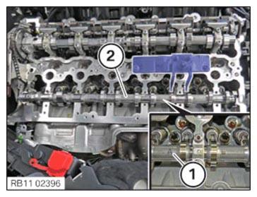
- Coat all bearing positions (arrows) with motor oil.
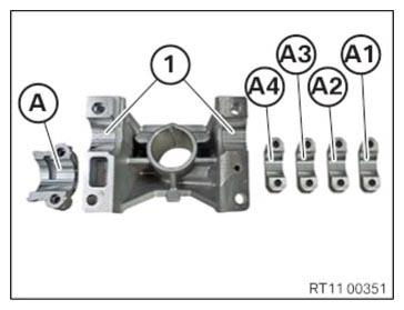
- Clean all bearing positions of the exhaust camshaft bearing caps (A1), (A2), (A3), (A4) and (A) and coat with motor oil.
- Clean the bearing positions (1) of the high pressure pump bracket and coat with motor oil.
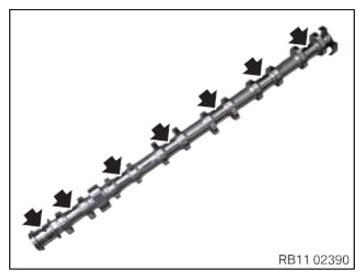
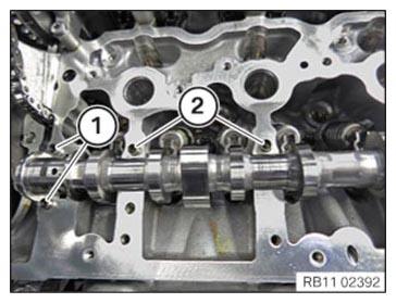
- Clean all the bearing positions (arrows) of the exhaust camshaft.
- Coat all bearing positions (arrows) of the exhaust camshaft with motor oil.
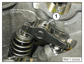
- Check all roller cam follower (1) of the exhaust side for correct fit.
- Insert the exhaust camshaft (2) in the cylinder head, so that the mark (1) points upwards.
- Check the fitting sleeves (1) of the thrust bearing for damage, replace if necessary.
- Check the fitting sleeves (2) of the high pressure pump bracket for damage, replace if necessary.NOTE: RISK OF DAMAGE
Engine damage caused by incorrectly installed bearing shells and bearing brackets.
If the bearing shells and bearing brackets are installed incorrectly, then engine damage can occur.- Always install all bearing shells and bearing brackets in the same position from which they were removed.
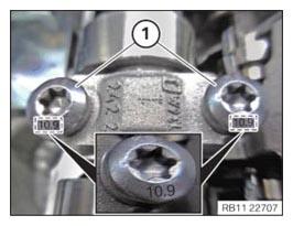
- Replace all exhaust camshaft bearing cap so that the labeling (1) from the intake side are readable.NOTE: TECHNICAL INFORMATION
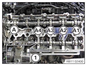
The camshaft bearing caps must not be mixed up. The camshaft bearing caps must be installed in the installation position from which they were removed. - Oil all the exhaust camshaft bearing caps (A1) to (A4) and the exhaust camshaft bearing cap for the thrust bearing (A) with motor oil and place into position.
- Oil the bearing position at the high pressure pump bracket with motor oil and place the high pressure pump bracket into position.
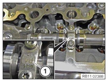
- Check the tensile strength of the screws for the bearing caps.
The illustration shows the screw with a tensile strength of 8.8.
- Check the tensile strength of the screws for the bearing cap.
The illustration shows the screw with a tensile strength of 10.9.
NOTE: TECHNICAL INFORMATION
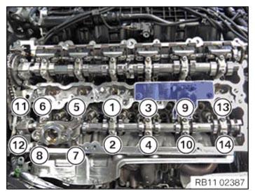
The camshaft is under tension due to the valve springs. Tighten or loosen each screw on the camshaft bearing caps in the prescribed sequence only by half a turn. Repeat procedure. - Press the exhaust camshaft bearing cap down and hand-tighten the screws incrementally in sequence (1) to (14).
- Abut all screws in the sequence from (1) to (14) in half turns.
- Observe the joining torque.
- Tighten
all screws in a sequence from (1) to (14).TIGHTENING TORQUES SPECIFICATION
Exhaust camshaft to cylinder head M6
Tensile strength of screw 8.8Joining torque 9.6 Nm tightening torque 9.6 Nm M6
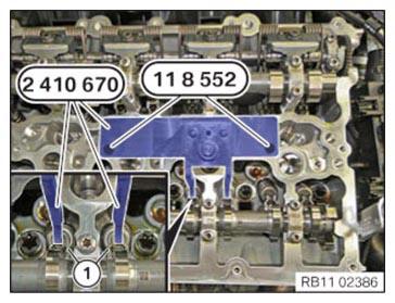
Tensile strength of screw 10.9Joining torque 11.8 Nm tightening torque 11.8 Nm - Relax special tool 2 410 670 above the spindle nut.
- Release special tools 0 495 741 (11 8 552)
and
remove the special tool 2 410 670.
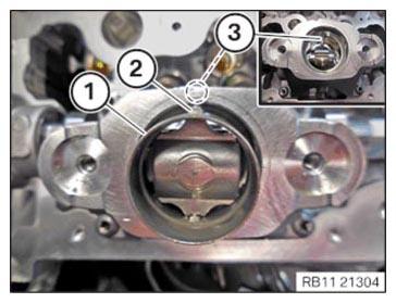
- Position and install the roller tappet (1).
- Make sure the pin (2) is correctly positioned in the guide (3).
- Insert and install the roller tappet (1).

Follow-up work
- Refer to ADJUSTING THE CAMSHAFTS WITH THE SPECIAL TOOL .
- Refer to INSTALLING EXHAUST CAMSHAFT ADJUSTER .
- Refer to INSTALLING THE VANOS CENTRAL VALVE OF THE EXHAUST CAMSHAFT ADJUSTER .
- Refer to RELEASING THE VANOS CENTRAL VALVE OF THE INTAKE ADJUSTER .
- Refer to INSTALLING THE VANOS CENTRAL VALVE OF THE INTAKE ADJUSTER .
- Refer to PRE-TENSIONING THE TIMING CHAIN WITH THE SPECIAL TOOL .
- Refer to TIGHTENING THE VANOS CENTRAL VALVE OF THE EXHAUST CAMSHAFT ADJUSTER .
- Refer to TIGHTENING THE VANOS CENTRAL VALVE OF THE INTAKE ADJUSTER .
- Refer to DISASSEMBLING ALL SPECIAL TOOLS .
- Refer to INSTALLING CHAIN TENSIONER .
- Refer to CHECKING THE TIMINGS OF THE CAMSHAFT .
- Refer to INSTALLING CYLINDER HEAD COVER .
- Refer to INSTALLING BOTH ACTUATORS .
- Refer to PREPARING THE INJECTORS FOR INSTALLATION .
- Refer to INSTALLING THE HIGH-PRESSURE RAIL WITH INJECTORS OF THE CYLINDERS 4 TO 6 .
- Refer to INSTALLING RAIL WITH INJECTORS OF CYLINDERS 1 TO 3 .
- Refer to INSTALLING HIGH PRESSURE PUMP .
- Refer to INSTALLING FUEL DELIVERY LINE .
- Refer to INSTALLING THE HIGH-PRESSURE LINE BETWEEN THE HIGH-PRESSURE PUMP AND THE HIGH-PRESSURE RAIL .
- Refer to INSTALLING ALL SPARK PLUGS .
- Refer to INSTALLING ALL IGNITION COILS .
- Refer to INSTALLING ACOUSTIC COVER AT REAR .
- Refer to INSTALLING THE CENTER COWL UPPER PART .
- Refer to INSTALLING TENSION STRUT ON SHOCK TOWER .
- Refer to INSTALLING WINDSHIELD PANEL COVER .
- Refer to INSTALLING LEFT AND RIGHT WIPER ARM .
- Refer to INSTALLING THE REAR RIGHT ENGINE COMPARTMENT COVER .
- Refer to INSTALLING THE COVER OF THE ENGINE COMPARTMENT ON THE REAR LEFT .
- Refer to INSTALLING THE FRONT HOOD SEAL AT THE REAR .
- Refer to INSTALLING FAN COWL .
- Refer to INSTALLING THE REAR TOP CROSS CONNECTION .
- Refer to INSTALLING FRONT CROSS CONNECTION .
- Refer to INSTALLING THE RESONATOR WITH THE TOP CLEAN AIR PIPE .
- Refer to INSTALLING THE INTAKE FILTER HOUSING (TENSION STRUT REMOVED ON SHOCK TOWER) .
- Refer to INSTALLING BOTH FRONT-END STRUTS .
- Refer to INSTALLING THE COVER ON THE LEFT AND RIGHT IN THE ENGINE COMPARTMENT AT THE TOP .
- Refer to CONNECTING NEGATIVE BATTERY CABLE .
- Refer to INSTALLING THE FRONT UNDERBODY PROTECTION OR FRONT THRUST FIELD .
- Refer to INSTALLING THE UNDERBODY PROTECTION OF THE STEERING GEAR OR THE FRONT THRUST FIELD .
- Refer to INSTALLING THE THRUST FIELD .
- Refer to INSTALLING REAR UNDERBODY PROTECTION .
- Refer to INSTALLING ACOUSTIC COVER .
- Refer to TAKING HOOD OUT OF THE SERVICE POSITION .