Remove cylinder head
WARNING:
Working on 12 V electrical system.
Risk of short circuits! Risk of fire!
Risk of short circuits! Risk of fire!
- Make sure that there is no charger connected to the jump start terminal in the engine compartment.
- Detach battery ground lead from battery.
- For auxiliary batteries: Detach battery minus cables from all auxiliary batteries.
WARNING:
Working on fuel system.
Risk of fire! Danger of explosion!
Risk of fire! Danger of explosion!
- When working on the fuel system, make sure the workstation has sufficient ventilation, e.g., by means of extraction.
- Tightly seal off open lines and connections; collect any leakage fuel directly at the point of exit.
- No fire, sparks, open flames or smoking.
CAUTION:
On releasing high pressure line, fuel may emerge at high speed.
Injury hazard!
Injury hazard!
- Wear suitable personal protective equipment.
- Before performing any installation work, allow cooling system to cool down to less than 40°C.
- Note warnings on cylinder head cover.
NOTE:
RISK OF DAMAGE
Damage to battery terminal, the safety battery terminal or the intelligent battery sensor (IBS).
Damaged battery terminals can lead to malfunctions or vehicle electrical system faults.
Damage to battery terminal, the safety battery terminal or the intelligent battery sensor (IBS).
Damaged battery terminals can lead to malfunctions or vehicle electrical system faults.
- Detach battery terminal from battery pole by carefully shifting to and fro. Do not pry off using a tool.
NOTE:
RISK OF DAMAGE
Engine damage due to missing motor oil.
Missing motor oil following replacement of the cylinder head or the engine can lead to damage on the valve train.
Engine damage due to missing motor oil.
Missing motor oil following replacement of the cylinder head or the engine can lead to damage on the valve train.
- After replacing the cylinder head or the engine, do not start the engine without observing the repair notes.
- It is imperative you observe the repair notes for cylinder head or engine replacement.
- For additional information, see: REPAIR NOTES FOR CYLINDER HEAD OR ENGINE REPLACEMENT
NOTE:
TECHNICAL INFORMATION
After replacing the motor or cylinder head: Reprogram or encode the digital motor electronics (DME) if necessary.
Read out the vehicle I-level and proceed accordingly.
Be absolutely certain to pay attention to PuMA measure 62634754.
For further information, see the applicable BMW parts catalogue.
After replacing the motor or cylinder head: Reprogram or encode the digital motor electronics (DME) if necessary.
Read out the vehicle I-level and proceed accordingly.
Be absolutely certain to pay attention to PuMA measure 62634754.
For further information, see the applicable BMW parts catalogue.
NOTE:
TECHNICAL INFORMATION
Collect and dispose of emerging fluids. Observe country-specific waste disposal regulations.
Collect and dispose of emerging fluids. Observe country-specific waste disposal regulations.
Preliminary work
- Refer to DISCONNECTING ALL BATTERY GROUND LEADS .
- Refer to REMOVE THE COVER OF THE ENGINE COMPARTMENT AT THE REAR LEFT
- Refer to BRING FRONT COMPARTMENT LID IN THE SERVICE POSITION .
- Refer to REMOVE THE SEAL FOR THE HOOD REAR .
- Refer to REMOVING THE ACOUSTIC COVER .
- Refer to REMOVE LEFT AND RIGHT WIPER ARM .
- Refer to REMOVE THE COWL COVER .
- Refer to REMOVING TRAILING LINK AT SPRING BOLT .
- Refer to REMOVING THE COWL UPPER PART IN THE CENTER .
- Refer to INSTALLING ACOUSTIC COVER AT REAR .
- Refer to REMOVING THE SEALING FRAME ON LEFT AND RIGHT
- Refer to REMOVING THE CENTER BULKHEAD LOWER PART .
- Refer to REMOVING BOTH ACTUATORS .
- Refer to REMOVE IGNITION COILS .
- Refer to REPLACE SPARK PLUGS
- Refer to REMOVE FUEL DELIVERY LINE .
- Refer to REMOVE THE HIGH PRESSURE LINE BETWEEN THE RAIL AND THE HIGH PRESSURE PUMP .
- Refer to REMOVE HIGH PRESSURE PUMP .
- Refer to REMOVE THE INJECTORS FOR CYLINDERS 1 TO 3 .
- Refer to REMOVE THE INJECTORS FOR CYLINDERS 4 TO 6 .
- Refer to REMOVE TANK VENT VALVE .
- Refer to REMOVING THE DME CONTROL UNIT .
- Refer to REMOVE THE INTEGRATED POWER SUPPLY MODULE (PDM) .
- Refer to REMOVE CONTROL UNIT BRACKET .
- Refer to REMOVING THE COVER ON LEFT AND RIGHT IN THE ENGINE COMPARTMENT AT THE TOP .
- Refer to REMOVE THE LEFT AND RIGHT FRONT-END STRUT
- Refer to REMOVE FRONT CROSS CONNECTION .
- Refer to REMOVE THE REAR TOP CROSS CONNECTION .
- Refer to REMOVING THE FAN COWL .
- Refer to REMOVING INTAKE SILENCER HOUSING .
- Refer to REMOVING THE RESONATOR WITH THE TOP CLEAN AIR PIPE .
- Refer to REMOVE BOTTOM CLEAN AIR PIPE .
- Refer to REMOVE CHARGE AIR LINE
- Refer to REMOVE FRONT ENGINE ENCAPSULATION .
- Refer to REPLACING THE LAMBDA OXYGEN SENSOR
- REPLACING THE OXYGEN MONITOR SENSOR
- Refer to REMOVE THE FRONT UNDERBODY PROTECTION OR FRONT THRUST FIELD .
- Refer to REMOVING THE UNDERBODY PROTECTION OF THE STEERING GEAR AND THRUST FIELD RESPECTIVELY .
- Refer to REMOVING THE STIFFENING PLATE .
- Refer to REMOVING STARTER MOTOR .
- Refer to REMOVE THE CONNECTING SUPPORT FROM THE TUNNEL .
- Refer to REMOVE COMPLETE EXHAUST SYSTEM .
- Refer to DRAINING THE MOTOR OIL .
- Refer to TIGHTENING THE OIL DRAIN PLUG .
- Refer to DRAIN THE COOLANT FROM THE HIGH-TEMPERATURE COOLING SYSTEM .
- Refer to DRAIN THE COOLANT FROM THE LOW-TEMPERATURE COOLING SYSTEM .
- Refer to REMOVING CATALYTIC CONVERTER .
- Refer to REMOVING THE EXHAUST TURBOCHARGER SUPPORT .
- Refer to REMOVING THE OIL RETURN LINE FOR THE EXHAUST TURBOCHARGER .
- Refer to REMOVING THE INTAKE PLENUM .
- Refer to REMOVING THE AUXILIARY COOLANT PUMP .
- Refer to REMOVING THE CYLINDER HEAD COVER .
- Refer to TURNING THE ENGINE ON THE VIBRATION DAMPER
- Refer to BLOCKING THE CRANKSHAFT IN THE TDC FIRING POSITION OF THE FIRST CYLINDER (AUTOMATIC TRANSMISSION) .
- Refer to BLOCKING THE CAMSHAFTS .
- Refer to REMOVING CHAIN TENSIONER .
- Refer to RELEASING THE VANOS CENTRAL VALVE .
- Refer to REMOVING INTAKE ADJUSTER .
- Refer to REMOVE EXHAUST CAMSHAFT ADJUSTER .
- Refer to DISASSEMBLING THE SPECIAL TOOL 2 358 122 .
- Refer to REMOVING THE FRONT SECTION OF THE COOLANT RETURN LINE .
- Refer to REMOVE THE REAR SECTION OF THE COOLANT RETURN LINE (FRONT SECTION IS REMOVED) .
- Refer to REMOVE THE COOLANT FEED LINE (COOLANT RETURN LINE IS REMOVED) .
- Refer to DETACH OIL SUPPLY LINE FROM THE ENGINE BLOCK .
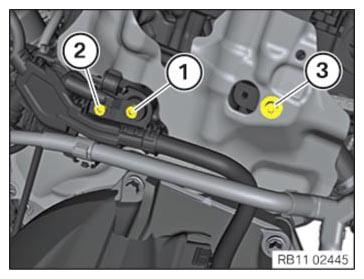
- Release screw (1) and lay the grounding cable to one side.
- Remove screw (2) and lay the wiring harness to one side.
- Release screw (3) and push the acoustic cover carefully towards the rear.
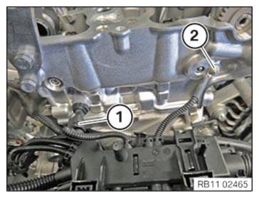
- Unlock and disconnect connector (1).
- Release screw (2) and lay the grounding cable to one side.
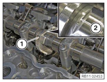
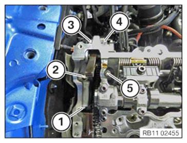
- Rotate intake camshaft, if necessary in the position shown.
The recess (2) must point up.
- Loosen screw (1).
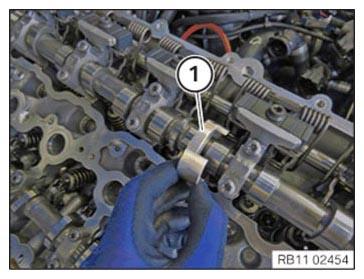
- Shift camshaft sensor wheel (1) in direction of cylinder 1 and feed out from the intake camshaft.
- Unscrew bolts (1) to (5).
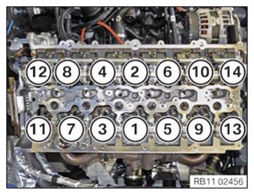
- Undo the screws using the special tool 0 495 747 (11 8 580) in the order (14) to (1).
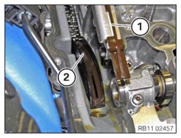
- Detach timing chain from the guide rail (1).
- Feed out guide rail (2) when removing the cylinder head.
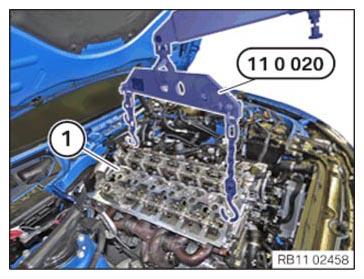
- Attach special tool 0 490 567 (11 0 020) to workshop crane.
- Lift out the cylinder head (1) and the exhaust turbocharger with the help of a second person, using the workshop crane and the special tool 0 490 567 (11 0 020).