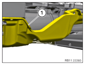
Install the acoustic cover for the oil sump
- Insert and position the acoustic cover (1) of the oil pan.
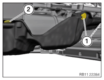
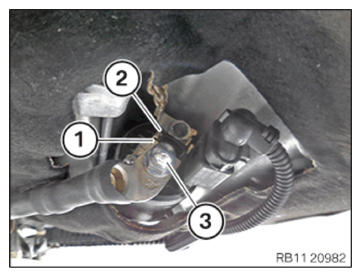
- Secure expanding rivet (1).
- Replace the Christmas tree clip (2).
Parts : Christmas Tree clip
- Attach the Christmas tree clip (2).
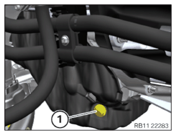
- Secure expanding rivet (1).
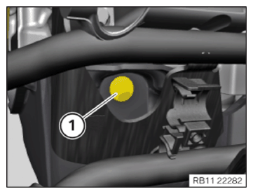
- Secure expanding rivet (1).
NOTE:
The following step(s) must be performed if the listed component(s) is/are installed.
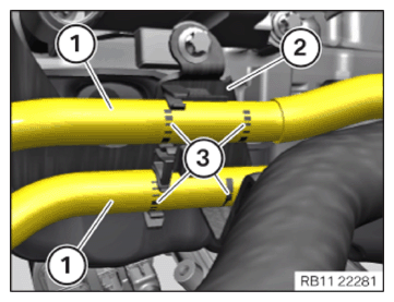
- Position the transmission oil lines (1) on the bracket (2).
Make sure the marks (3) are positioned correctly on the holder (2).
NOTE:
The following step(s) must be performed if the listed component(s) is/are installed.
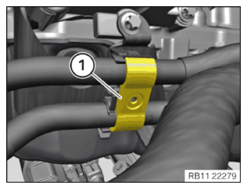
- Insert and install the holder (1).
NOTE:
The following step(s) must be performed if the listed component(s) is/are installed.
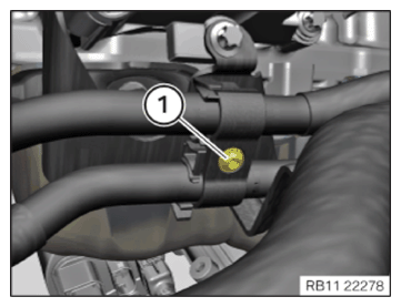
- Tighten down screw (1).
TIGHTENING TORQUES SPECIFICATION
| Holder for transmission oil line | ||
| Screw | Tightening torque | 4 Nm |
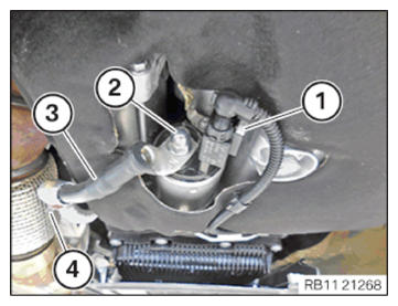
- Connect and lock the connector (1).
- Make sure the connector (1) engages audibly.
- Insert and install the positive battery cable (3).
- Secure positive battery cable (3) at the clamp (4).
- Tighten the nut (2) hand-tight.
CAUTION:
Improper routing of the positive battery cable.
Risk of short circuits!
Risk of short circuits!
- Route the positive battery cable without abrasions and do not trap.
- Correctly attach the positive battery cable (1) to the anti-twist lock (2).
- Tighten the nut (3).
TIGHTENING TORQUES SPECIFICATION
| Battery positive lead to starter | ||
| M8 | Tightening torque | 13.5 Nm |
Follow-up work
- Refer to RAISE FRONT AXLE SUPPORT .
- Refer to TIGHTEN THE SCREWS ON THE LEFT AND RIGHT FRONT AXLE SUPPORT .
- Refer to SECURE THE SPRING STRUT ON THE WISHBONE ON THE BOTTOM LEFT AND RIGHT .
- Refer to SECURE THE WISHBONE ON THE TOP LEFT AND RIGHT ON THE SWIVEL BEARING .
- Refer to REMOVING THE MOBILE LIFTING TABLE .
- Refer to IF INSTALLED: CONNECT THE CONNECTOR OF THE ACTIVE STABILIZER
- Refer to SECURING BRAKE HOSE, FRONT RIGHT AND LEFT .
- Refer to SECURING THE ANTI-ROLL BAR LINK ON THE LEFT AND RIGHT TO THE ANTI-ROLL BAR .
- Refer to IF INSTALLED: INSTALL THE SILENCER OF THE STATIONARY HEATING (ADDITIONAL WORK FRU NO.: 31 11 905) .
- Refer to INSTALL LEFT AND RIGHT BRAKE VENTILATION DUCT .
- Refer to SECURE THE WIRING HARNESS FOR THE EPS ON THE FRONT AXLE SUPPORT .
- Refer to INSTALL THE REINFORCEMENT STRUT ON THE ENGINE MOUNT ON THE LEFT AND RIGHT
- Refer to TAKE ENGINE OUT OF INSTALLATION ORIENTATION .
- Refer to INSTALL THE WHEEL ARCH COVER ON THE FRONT LEFT AND BOTTOM RIGHT
- Refer to INSTALL THE REAR SECTION OF THE FRONT WHEEL ARCH COVER ON THE LEFT AND RIGHT .
- Refer to INSTALL THE COVER OF THE STEERING ASSEMBLY ON THE LEFT AND RIGHT .
- Refer to INSTALL THE FRONT LEFT AND RIGHT WHEELS .
- Refer to INSTALL CLEAN AIR PIPE, TOP .
- Refer to INSTALLING INTAKE SILENCER HOUSING .
- Refer to INSTALLING THE COVER ON THE LEFT AND RIGHT IN THE ENGINE COMPARTMENT AT THE TOP
- Refer to INSTALLING THE SIDE HOOD SEAL ON THE LEFT AND RIGHT .
- Refer to INSTALL THE REAR RIGHT ENGINE COMPARTMENT COVER .
- Refer to INSTALL THE COVER OF THE ENGINE COMPARTMENT ON THE REAR LEFT .
- Refer to INSTALLING ACOUSTIC COVER .
- Refer to INSTALL REAR UNDERBODY PROTECTION .
- Refer to INSTALL THE CENTER UNDERBODY PROTECTION .
- Refer to INSTALLING THE UNDERBODY PROTECTION OF THE STEERING GEAR OR THE FRONT THRUST FIELD .
- Refer to INSTALL THE FRONT UNDERBODY PROTECTION OR FRONT THRUST FIELD .
- Refer to CONNECTING NEGATIVE BATTERY CABLE .
- Refer to ACTIVATING THE 48 V ELECTRICAL SYSTEM .
- Refer to TAKE HOOD OUT OF THE SERVICE POSITION .