Determining the classification of the crankshaft main bearing shell
CAUTION:
Component with heavy weight.
Injury hazard!
- Note component's center of gravity.
- Support component using a jack.
- Secure component against falling off the jack.
CAUTION:
On releasing high pressure line, fuel may emerge at high speed.
Injury hazard!
- Wear suitable personal protective equipment.
- Before performing any installation work, allow cooling system to cool down to less than 40°C.
- Note warnings on cylinder head cover.
NOTE:
TECHNICAL INFORMATION
Collect and dispose of emerging fluids. Observe country-specific waste disposal regulations.
Collect and dispose of emerging fluids. Observe country-specific waste disposal regulations.
Preliminary work
- Refer to REMOVING ENGINE .
- Refer to INSTALLING THE ENGINE ON THE ASSEMBLY STAND
- Refer to RELEASING THE OIL DRAIN PLUG .
- Refer to TIGHTENING THE OIL DRAIN PLUG .
- Refer to REMOVING ALL SPARK PLUGS .
- Refer to REMOVE THE HIGH PRESSURE LINE BETWEEN THE HIGH PRESSURE PUMP AND THE RAIL .
- Refer to REMOVE HIGH PRESSURE PUMP .
- Refer to REMOVING THE RAIL WITH INJECTORS .
- Refer to REMOVING BOTH ACTUATORS .
- Refer to REMOVING THE CYLINDER HEAD COVER .
- Refer to REMOVE TANK VENT VALVE .
- Refer to REMOVING THE INTAKE PLENUM .
- Refer to REMOVE THE HEAT SHIELD AT THE CYLINDER HEAD
- Refer to REMOVING THE OIL RETURN LINE FOR THE EXHAUST TURBOCHARGER .
- Refer to REMOVE THE COOLANT RETURN LINE FOR THE EXHAUST TURBOCHARGER .
- Refer to REMOVE THE COOLANT FEED LINE FOR THE EXHAUST GAS TURBOCHARGER .
- Refer to BLOCKING ENGINE IN TDC FIRING POSITION .
- Refer to REMOVING CHAIN TENSIONER .
- Refer to RELEASING THE VANOS CENTRAL VALVE OF THE INTAKE ADJUSTER .
- Refer to RELEASING VANOS CENTRAL VALVE OF THE EXHAUST CAMSHAFT ADJUSTER .
- Refer to REMOVING THE VANOS CENTRAL VALVE OF THE INTAKE ADJUSTER .
- Refer to REMOVING THE VANOS CENTRAL VALVE OF THE EXHAUST CAMSHAFT ADJUSTER .
- Refer to REMOVING INTAKE ADJUSTER .
- Refer to REMOVE EXHAUST CAMSHAFT ADJUSTER .
- Refer to REMOVE THE TEST GAUGES FOR SECURING THE CAMSHAFTS .
- Refer to REMOVING THE CYLINDER HEAD .
- Refer to REMOVING THE CYLINDER HEAD GASKET .
- Refer to REMOVING THE ACOUSTIC COVER OF THE OIL SUMP .
- Refer to REMOVING THE VIBRATION DAMPER .
- Refer to REMOVING FLYWHEEL .
- Refer to REMOVE OIL SUMP .
- Refer to REMOVE REAR TIMING CASE COVER .
- Refer to REMOVING TIMING CHAIN .
- Refer to REMOVE THE OIL VACUUM PUMP .
- Refer to REMOVING THE OIL DEFLECTOR
- Refer to REMOVING ALL PISTONS WITH CONNECTING ROD .
- Refer to REMOVING CRANKSHAFT .
NOTE:
TECHNICAL INFORMATION
The main bearing shells and guide bearing shells are still classified by colors or numbers.
The classification of the main bearing shells and guide bearing shells is being changed to a classification using only numbers. The color classification is being dropped.
The main bearing shells and guide bearing shells are still classified by colors or numbers.
The classification of the main bearing shells and guide bearing shells is being changed to a classification using only numbers. The color classification is being dropped.
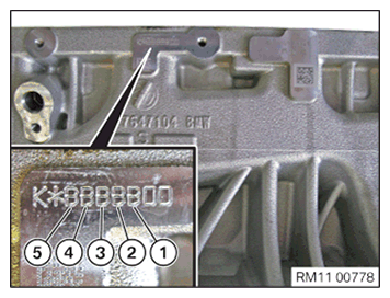
- Read off the code letters on the crankcase and enter them in the table.
K = Clutch side
Item numbers (5) to (1) describe the bearing seats 5 to 1. The code number on each of the crankshaft bearing caps.
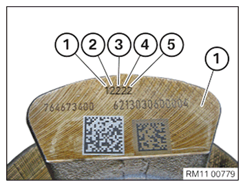
- Read off the code number on the crankshaft and enter it in the table.
Item numbers (1) to (5) describe the bearing seats 1 to 5. The code number on each of the crankshaft bearing caps.
- Enter the code letters from the crankcase.
- Enter the code numbers from the crankshaft.
| Code letters on the crankcase | Code number/letters on the crankshaft | |
|---|---|---|
| Bearing seat 1 | ||
| Bearing seat 2 | ||
| Bearing seat 3 | ||
| Bearing seat 4 | ||
| Bearing seat 5 |
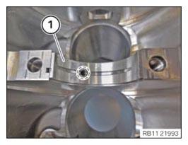
- Use the table to determine the correct main bearing shell with lubricated groove (1) for the crankcase.
The main bearing shells are classified by colors or numbers.
| A | B | C | |
|---|---|---|---|
| 1 | Classification 1 (blue) | Classification 2 (green) | Classification 2 (green) |
| 2 | Classification 1 (blue) | Classification 2 (green) | Classification 3 (brown) |
| 3 | Classification 2 (green) | Classification 2 (green) | Classification 3 (brown) |
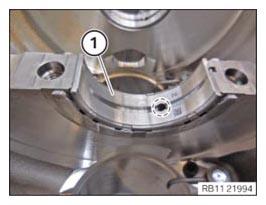
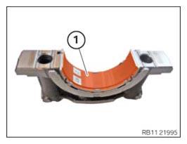
- Use the table to determine the correct guide bearing shell with lubricated groove (1) for the crankcase.
The guide bearing shells are classified by colors or numbers.
| A | B | C | |
|---|---|---|---|
| 1 | Classification 1 (blue) | Classification 2 (green) | Classification 2 (green) |
| 2 | Classification 1 (blue) | Classification 2 (green) | Classification 3 (brown) |
| 3 | Classification 2 (green) | Classification 2 (green) | Classification 3 (brown) |
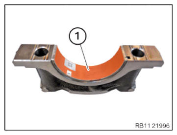
- Use the table to determine the correct main bearing shell without lubricated groove (1) for the crankcase.
The main bearing shells are classified by colors or numbers.
| A | B | C | |
|---|---|---|---|
| 1 | Classification 1 (blue) | Classification 1 (blue) | Classification 2 (green) |
| 2 | Classification 2 (green) | Classification 2 (green) | Classification 2 (green) |
| 3 | Classification 2 (green) | Classification 3 (brown) | Classification 3 (brown) |
- Use the table to determine the correct guide bearing shell without lubricated groove (1) for the crankcase.
The guide bearing shells are classified by colors or numbers.
| A | B | C | |
|---|---|---|---|
| 1 | Classification 1 (blue) | Classification 1 (blue) | Classification 2 (green) |
| 2 | Classification 2 (green) | Classification 2 (green) | Classification 2 (green) |
| 3 | Classification 2 (green) | Classification 3 (brown) | Classification 3 (brown) |