Install the piston rings
NOTE:
RISK OF DAMAGE
Very wide spreading of the piston rings during installation/removal.
Damage to the piston rings.
Very wide spreading of the piston rings during installation/removal.
Damage to the piston rings.
- Spread the piston rings only until the piston ring can just be slid over the piston.
- Use piston ring pliers to install and remove the piston rings.
NOTE:
TECHNICAL INFORMATION
Clean the used pistons carefully. Do not use a metal-cutting tool to avoid damaging the pistons.
Clean the used pistons carefully. Do not use a metal-cutting tool to avoid damaging the pistons.
NOTE:
TECHNICAL INFORMATION
Wear safety goggles.
Wear safety goggles.
NOTE:
The description is for one component only. The procedure is identical for all further components.
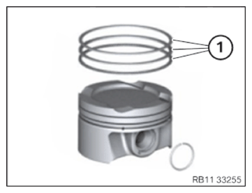
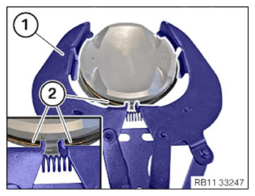
- Determining the correct set of the piston ring (1) (see applicable BMW parts catalogue):
Engine Set of piston rings Pistons B38M1 ECE 8 693 017 8 678 931 B38M1 ECE 8 693 017 9 494 399 B48M1 ECE 8 693 017 8 678 931 B48M1 ECE 8 693 017 9 494 399 B38M1 CN 8 693 017 8 678 931 B38M1 CN 9 847 276 8 681 079 B48M1 CN 8 693 017 8 678 931 B48M1 CN 9 847 276 8 681 079 B4801 ECE+CN 8 693 017 8 678 934 B48T1 ECE+CN 9 846 014 9 488 343 B58M1 9 847 276 8 681 079 B5801 9 693 017 8 678 934 - Keep the standard piston ring pliers (1) ready.
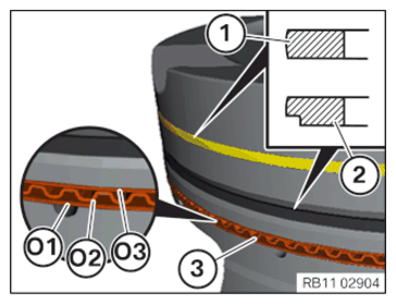
- Correctly prepare the piston rings:
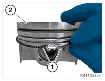
Upper piston ring (1): Plain rectangular compression ring (engraving must point upwards)
Center piston ring (2): Taper faced piston ring (engraving must point upwards)
Oil scraper ring (3): consists of 2 piston rings ((01), (03)) with a spring (02) in the center.
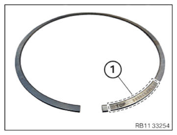
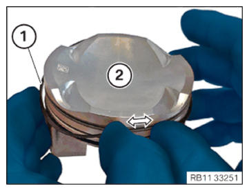
- Make sure that the assembly mark TOP (1) points to the top to the combustion chamber.
- If there is no assembly mark TOP
(1), then the piston ring with the writing must point to the top to the combustion chamber.
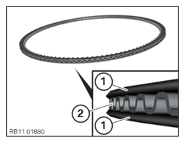
- Attach the oil scraper rings (1) and springs (2) manually (see following steps).
- Slide the spring (1) on to the piston (2) and install it.
- Slide the two oil scraper rings (1) on to the piston (2) and install them.
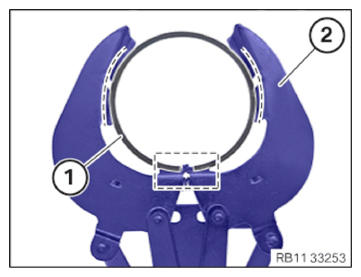
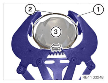
- Position the center piston ring (1) in the marked area
at the piston ring pliers (2).
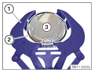
- Clamp the piston ring pliers (1) in arrow direction and feed in the center piston ring (2) in the piston (3) and install it.
- Release the piston ring pliers (1) at the center piston ring (2).
- Feed out the piston ring pliers (1) at the center piston ring (2) and remove it.
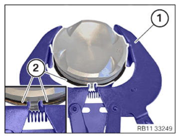
- Position the upper piston ring (1) in the marked area
at the piston ring pliers (2).
- Clamp the piston ring pliers (1) in arrow direction and feed in the upper piston ring (2) in the piston (3) and install it.
- Release the piston ring pliers (1) at the upper piston ring (2).
- Feed out the piston ring pliers (1) at the upper piston ring (2) and remove it.

Follow-up work
- Refer to INSTALLING ALL PISTONS WITH CONNECTING ROD .
- Refer to INSTALLING THE OIL DEFLECTOR
- Refer to PREPARING THE OIL VACUUM PUMP .
- Refer to INSTALL THE OIL VACUUM PUMP .
- Refer to INSTALLING THE OIL PAN .
- Refer to INSTALLING THE FLYWHEEL .
- Refer to INSTALLING THE ACOUSTIC COVER FOR THE OIL PAN .
- Refer to BLOCKING THE CRANKSHAFT IN THE TDC FIRING POSITION OF CYLINDER 1 .
- Refer to SEAL THE OIL DUCT .
- Refer to CLEAN SEALING SURFACES .
- Refer to REPLACE CYLINDER HEAD GASKET .
- Refer to INSTALLING THE CYLINDER HEAD .
- Refer to ADJUSTING THE CAMSHAFTS WITH THE SPECIAL TOOL .
- Refer to INSTALL EXHAUST CAMSHAFT ADJUSTER .
- Refer to INSTALLING THE INTAKE ADJUSTER .
- Refer to INSTALLING THE VANOS CENTRAL VALVE OF THE INTAKE ADJUSTER .
- Refer to INSTALLING THE VANOS CENTRAL VALVE OF THE EXHAUST CAMSHAFT ADJUSTER .
- Refer to PRE-TENSIONING THE TIMING CHAIN WITH THE SPECIAL TOOL .
- Refer to TIGHTENING THE VANOS CENTRAL VALVE OF THE EXHAUST CAMSHAFT ADJUSTER .
- Refer to TIGHTENING THE VANOS CENTRAL VALVE OF THE INTAKE ADJUSTER .
- Refer to DISASSEMBLING ALL SPECIAL TOOLS
- Refer to INSTALL CHAIN TENSIONER .
- Refer to CHECKING THE TIMINGS OF THE CAMSHAFT .
- Refer to INSTALLING THE OIL RETURN LINE FOR THE EXHAUST TURBOCHARGER .
- Refer to INSTALL THE COOLANT RETURN LINE FOR THE EXHAUST TURBOCHARGER .
- Refer to INSTALLING COOLANT FEED LINE FOR EXHAUST TURBOCHARGER .
- Refer to INSTALLING CYLINDER HEAD COVER .
- Refer to INSTALLING BOTH ACTUATORS .
- Refer to INSTALLING THE HEAT SHIELD ON THE CYLINDER HEAD
- Refer to PREPARE THE INJECTORS FOR INSTALLATION .
- Refer to INSTALLING THE RAIL WITH INJECTORS .
- Refer to INSTALLING HIGH PRESSURE PUMP .
- Refer to INSTALLING THE HIGH-PRESSURE LINE BETWEEN THE HIGH-PRESSURE PUMP AND THE HIGH-PRESSURE RAIL .
- Refer to INSTALLING ALL SPARK PLUGS .
- Refer to INSTALL INTAKE PLENUM .
- Refer to INSTALLING THE TANK VENT VALVE .
- Refer to TOPPING UP THE MOTOR OIL .
- Refer to REMOVING THE ENGINE FROM ASSEMBLY JIG
- Refer to INSTALL ENGINE .