Installing all intermediate levers
NOTE:
TECHNICAL INFORMATION
When replacing one or more intermediate levers:
When removing the intermediate lever, it is imperative to note the part number of the intermediate lever.
A mixed installation of intermediate levers is only permitted in combination with the appropriate torsion spring.
For further information on possible combinations, see the applicable BMW parts catalogue.
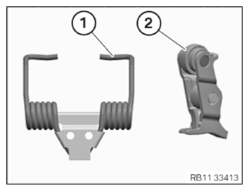
- Version with a torsion spring with an L-shaped contour and a suitable intermediate lever
Use a torsion spring (1) with L-shaped contour only in connection with the suitable intermediate lever (2).
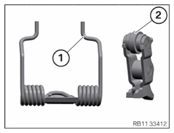
- Version with a torsion spring with an S-shaped contour and a suitable intermediate lever
Use a torsion spring (1) with the s-shaped contour only in connection with the suitable intermediate lever (2).
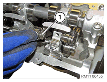
NOTE: The description is for one component only.
The procedure is identical for all further components. - Install the intermediate lever (1).
Follow-up work
- refer to CHECKING INSTALLATION POSITION OF ROLLER CAM FOLLOWERS .
- refer to INSTALLING ALL GATES .
- refer to CHECKING THE POSITION OF THE INTAKE CAMSHAFT .
- refer to CHECK THE POSITION OF THE INTAKE CAMSHAFT AT CYLINDER 3 AND 4 .
- refer to INSTALLING TORSION SPRINGS .
- Refer to INSTALLING THE INTAKE PLENUM .
- Refer to INSTALLING THE TANK VENT VALVE .
- Refer to INSTALLING THE CONTROL UNIT HOLDER .
- Refer to INSTALLING THE INTEGRATED POWER SUPPLY MODULE (PDM) .
- Refer to INSTALLING THE DME CONTROL UNIT .
- Refer to INSTALLING CYLINDER HEAD COVER .
- Refer to INSTALLING BOTH ACTUATORS .
- Refer to PREPARING THE INJECTORS FOR INSTALLATION .
- Refer to INSTALLING THE HIGH-PRESSURE RAIL WITH INJECTORS OF THE CYLINDERS 4 TO 6 .
- Refer to INSTALLING RAIL WITH INJECTORS OF CYLINDERS 1 TO 3 .
- Refer to INSTALLING HIGH PRESSURE PUMP .
- Refer to INSTALLING FUEL DELIVERY LINE .
- Refer to INSTALLING THE HIGH-PRESSURE LINE BETWEEN THE HIGH-PRESSURE PUMP AND THE HIGH-PRESSURE RAIL .
- Refer to INSTALLING ALL IGNITION COILS .
- Refer to INSTALLING ACOUSTIC COVER AT REAR .
- Refer to INSTALLING THE CENTER COWL UPPER PART .
- Refer to INSTALLING TENSION STRUT ON SHOCK TOWER .
- Refer to INSTALLING WINDSHIELD PANEL COVER .
- Refer to INSTALLING LEFT AND RIGHT WIPER ARM .
- Refer to INSTALLING THE REAR RIGHT ENGINE COMPARTMENT COVER .
- Refer to INSTALLING THE COVER OF THE ENGINE COMPARTMENT ON THE REAR LEFT .
- Refer to INSTALLING THE FRONT HOOD SEAL AT THE REAR .
- Refer to INSTALLING FAN COWL .
- Refer to INSTALLING THE REAR TOP CROSS CONNECTION .
- Refer to INSTALLING FRONT CROSS CONNECTION .
- Refer to INSTALLING THE RESONATOR WITH THE TOP CLEAN AIR PIPE .
- Refer to INSTALLING THE INTAKE FILTER HOUSING (TENSION STRUT REMOVED ON SHOCK TOWER) .
- Refer to INSTALLING BOTH FRONT-END STRUTS .
- Refer to INSTALLING THE COVER ON THE LEFT AND RIGHT IN THE ENGINE COMPARTMENT AT THE TOP .
- Refer to FILLING THE LOW-TEMPERATURE COOLING SYSTEM WITH THE VACUUM FILLING EQUIPMENT .
- Refer to CONNECTING NEGATIVE BATTERY CABLE .
- Refer to VENTING THE LOW-TEMPERATURE COOLING SYSTEM .
- Refer to INSTALLING THE FRONT UNDERBODY PROTECTION OR FRONT THRUST FIELD .
- Refer to INSTALLING THE UNDERBODY PROTECTION OF THE STEERING GEAR OR THE FRONT THRUST FIELD .
- Refer to INSTALLING ACOUSTIC COVER .
- Refer to TAKING HOOD OUT OF THE SERVICE POSITION .