Installing the flywheel
NOTE:
TECHNICAL INFORMATION
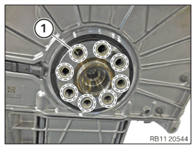
Clean all threads with a screw tap.
Clean all threads with a screw tap.
- Clean all the screw threads (1).
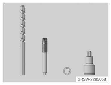
- Use set of special tools 2 285 058.
Description Twist drill Thread cutter M12x1.5 Deep stop Screw in tool - Assemble tool set.
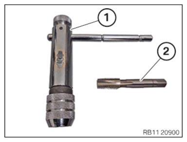
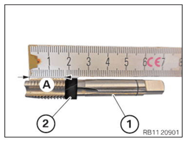
Number Description 1 Tool holder 2 Thread cutter M12X1.5 - Mark screwing depth (A) on the thread cutter (1) from the special tool set 2 285 058
with a commercially available tool (2).TECHNICAL DATA - SCREW-IN DEPTH SPECIFICATION
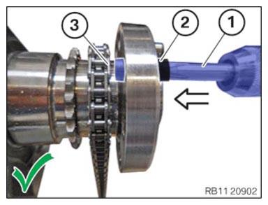
Screw-in depth of thread cutter Screw-in depth 18 mm NOTE: To provide a better overview: Shown with engine removed. - Screw in the thread cutter (1) from the set of special tools 2 285 058
in arrow direction up to the screw-in depth (2).TECHNICAL DATA - SCREW-IN DEPTH SPECIFICATION
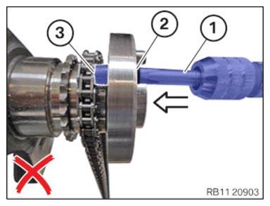
Screw-in depth of thread cutter Screw-in depth 18 mm - Make sure that the thread cutter is (1 ) not
pressed up against the timing chain (3).NOTE: TECHNICAL INFORMATION
Handle the timing chain carefully to protect the timing chain and timing chain drive from damage. - Make sure that the screw-in depth (2) of the screw tap (1) is not exceeded.
The thread cutter (1) must not come into contact with the timing chain (3).
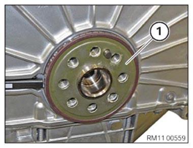
- Note the installation position of the magnet wheel (1).
- Position the magnet wheel (1) on the crankshaft.
- Replace screws (1) to (8).
Parts: Screws
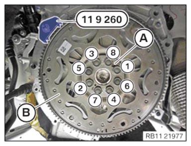
- Position the flywheel (B).
- Screw in flywheel bolt (1) to (8) by hand.
- Set flywheel (B) with the special tool 0 494 034 (11 9 261) and screw tight with the special tool 0 494 130 (11 9 264).
- Make sure that the tightening sequence takes place from the dowel pin (A).
- Tighten the flywheel bolts in the sequence (1) to (8) (note the angle of rotation in the next step).TIGHTENING TORQUES SPECIFICATION
Flywheel to crankshaft M 12x1.5
Replace screws.Tightening torque
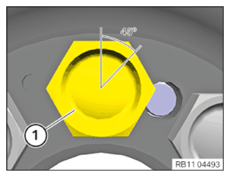
Angle of rotation45 Nm
45° - Apply all flywheel bolts (1) with an angle of rotation of 45° with the help of the special tool 0 490 504 (00 9 120). NOTE: Mark all flywheel bolts (1) with a vertical line.
- Remove special tool 0 493 938 (11 9 260).
Follow-up work
- Refer to INSTALLING AUTOMATIC TRANSMISSION (ALL-WHEEL DRIVE VEHICLE) (GA8HP51Z) .
- Refer to INSTALLING STARTER MOTOR
- Refer to INSTALL THE ACOUSTIC COVER FOR THE OIL SUMP .
- Refer to FASTENING THE PROP SHAFT (PARTIALLY REMOVED)
- Refer to INSTALL THE RETAINING PLATES .
- Refer to INSTALLING THE HEAT SHIELDS
- Refer to INSTALLING THE COMPLETE EXHAUST SYSTEM .
- Refer to IF INSTALLED: INSTALL THE TORSION STRUT ON THE RIGHT, AND ON THE LEFT WHERE REQUIRED .
- Refer to INSTALL THE CONNECTING SUPPORTS ON THE TUNNEL .
- Refer to INSTALL FAN COWL .
- Refer to INSTALL THE REAR TOP CROSS CONNECTION .
- Refer to INSTALL FRONT CROSS CONNECTION .
- Refer to INSTALLING BOTH FRONT-END STRUTS
- Refer to INSTALLING THE COVER ON THE LEFT AND RIGHT IN THE ENGINE COMPARTMENT AT THE TOP
- Refer to CONNECTING NEGATIVE BATTERY CABLE .
- Refer to ACTIVATING THE 48 V ELECTRICAL SYSTEM .
- Refer to CHECKING/TOPPING UP THE OIL LEVEL IN THE AUTOMATIC TRANSMISSION .
- Refer to INSTALLING ACOUSTIC COVER .
- Refer to INSTALL THE THRUST FIELD .
- Refer to INSTALLING THE UNDERBODY PROTECTION OF THE STEERING GEAR OR THE FRONT THRUST FIELD .
- Refer to INSTALL REAR UNDERBODY PROTECTION .
- Refer to INSTALL THE FRONT UNDERBODY PROTECTION OR FRONT THRUST FIELD .
- Refer to TAKE HOOD OUT OF THE SERVICE POSITION .