Remove crankshaft
CAUTION:
Component with heavy weight.
Danger of injury!
Danger of injury!
- Note component's center of gravity.
- Support component using a jack.
- Secure component against falling off the jack.
CAUTION:
On releasing high pressure line, fuel may emerge at high speed.
Danger of injury!
Danger of injury!
- Wear suitable personal protective equipment.
- Allow the cooling system to cool down to a temperature below 40°C before starting installation work.
- Note warnings on cylinder head cover.
NOTE:
TECHNICAL INFORMATION
Collect and dispose of emerging fluids. Observe country-specific waste disposal regulations.
Collect and dispose of emerging fluids. Observe country-specific waste disposal regulations.
Preliminary works
- Refer to REMOVING ENGINE .
- Refer to INSTALLING THE ENGINE ON THE ASSEMBLY STAND
- Refer to RELEASING THE OIL DRAIN PLUG .
- Refer to TIGHTENING THE OIL DRAIN PLUG .
- Refer to REMOVING ALL SPARK PLUGS .
- Refer to REMOVE THE HIGH PRESSURE LINE BETWEEN THE HIGH PRESSURE PUMP AND THE RAIL .
- Refer to REMOVE HIGH PRESSURE PUMP .
- Refer to REMOVING THE RAIL WITH INJECTORS .
- Refer to REMOVING BOTH ACTUATORS .
- Refer to REMOVING THE CYLINDER HEAD COVER .
- Refer to REMOVE TANK VENT VALVE .
- Refer to REMOVING THE INTAKE PLENUM .
- Refer to REMOVE THE HEAT SHIELD AT THE CYLINDER HEAD
- Refer to REMOVING THE OIL RETURN LINE FOR THE EXHAUST TURBOCHARGER .
- Refer to REMOVE THE COOLANT RETURN LINE FOR THE EXHAUST TURBOCHARGER .
- Refer to REMOVE THE COOLANT FEED LINE FOR THE EXHAUST GAS TURBOCHARGER .
- Refer to BLOCKING ENGINE IN THE TDC FIRING POSITION .
- Refer to REMOVING CHAIN TENSIONER .
- Refer to RELEASING THE VANOS CENTRAL VALVE OF THE INTAKE ADJUSTER .
- Refer to RELEASING VANOS CENTRAL VALVE OF THE EXHAUST CAMSHAFT ADJUSTER .
- Refer to REMOVING THE VANOS CENTRAL VALVE OF THE INTAKE ADJUSTER .
- Refer to REMOVING THE VANOS CENTRAL VALVE OF THE EXHAUST CAMSHAFT ADJUSTER .
- Refer to REMOVING INTAKE ADJUSTER .
- Refer to REMOVE EXHAUST CAMSHAFT ADJUSTER .
- Refer to REMOVE THE TEST GAUGES TO FIX THE CAMSHAFTS .
- Refer to REMOVING THE CYLINDER HEAD .
- Refer to REMOVING THE CYLINDER HEAD GASKET .
- Refer to REMOVING THE ACOUSTIC COVER OF THE OIL SUMP .
- Refer to REMOVING THE VIBRATION DAMPER .
- Refer to REMOVING FLYWHEEL .
- Refer to REMOVE FRONT AXLE DIFFERENTIAL .
- Refer to REMOVE BEARING SUPPORT .
- Refer to REMOVE OIL PAN
- Refer to REMOVE REAR TIMING CASE COVER .
- Refer to REMOVING TIMING CHAIN .
- Refer to REMOVE THE OIL VACUUM PUMP .
- Refer to REMOVING THE OIL DEFLECTOR
- Refer to REMOVING ALL PISTONS WITH CONNECTING ROD .
NOTE:
In the following operations, the engine is rotated by 180 degrees. The bottom points up.
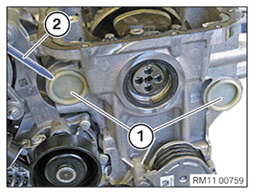
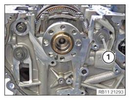
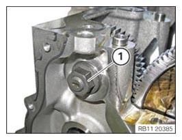
- Remove both sealing caps (1) with a suitable tool (2).
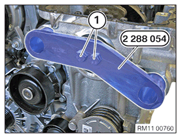
- Rotate the crankshaft to the TDC of the first cylinder.
- Mount the special tool 2 288 054 and abut the bolts (1).
NOTE:
The description is for one component only. The procedure is identical for all further components.
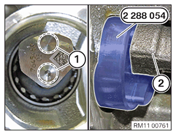
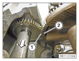
- Make sure the special tool 2 288 054 is correctly fitted in the guides (1) of the counterbalance shafts (2).
- If necessary, turn the crankshaft slightly.
- Tighten special tool 2 288 054 .
TIGHTENING TORQUES SPECIFICATION
| Special tool 2 288 054 to crankshaft | ||
| Tightening torque | 20 Nm | |
- Loosen screws (1) on the counterbalance shaft on the intake side.
- Loosen screws (1).
- Guide the special tool 2 288 054
out and remove.
- Guide out counterbalance shaft (1) on the intake side from crankshaft (2) in the direction of the arrow
.
- Carefully
place aside counterbalance shaft (1) on the intake side.
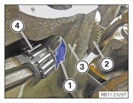
- Position a clean lint-free cleaning rag (1) between counterbalance shaft (2) on the intake side and crankcase (3).
- Ensure that needle bearing (4) is not damaged
.
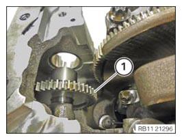
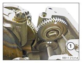
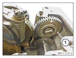
- Unfasten nut (1).
- Vehicles up to year of manufacture until 07/16
Thread out the intermediate wheel (1) and remove.
- Vehicles up to year of manufacture from 07/16
Thread out the intermediate wheel (1) and remove.
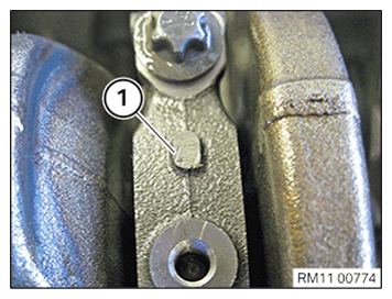
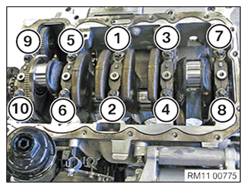
- Observe the numbering (1) of the main bearing caps.
The mounting orientation must be maintained.
- Loosen screws in the order (10) to (1).
- Place the main bearing cap neatly into the special tool 0 495 105 (11 4 480) .
CAUTION:
Heavy component.
Heavy components can lead to injury or damage.
Heavy components can lead to injury or damage.
- Remove and install heavy components with the aid of another person/other persons.
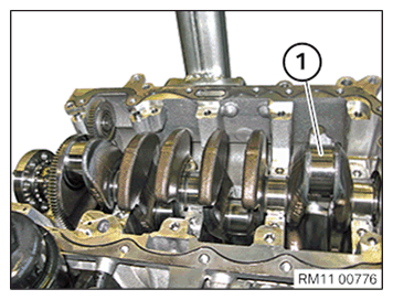
- Guide out and remove crankshaft (1).