Remove left cylinder head
Prerequisite
- Ignition is switched off.
WARNING:
Hot surfaces.
Risk of burning!
Risk of burning!
- Perform all work only on components that have cooled down.
WARNING:
Vehicle may slip off the vehicle hoist if the vehicle hoist is handled incorrectly.
Danger! Immobilization period-threatening injuries!
Danger! Immobilization period-threatening injuries!
- Observe safety instructions on raising the vehicle using a vehicle hoist.
- For additional information see: 00... RAISE THE VEHICLE USING A VEHICLE LIFT.
WARNING:
Working on 12 V electrical system.
Risk of short circuits! Risk of fire!
Risk of short circuits! Risk of fire!
- Make sure that there is no charger connected to the jump start terminal in the engine compartment.
- Detach battery ground lead from battery.
- For auxiliary batteries: Detach battery minus cables from all auxiliary batteries.
WARNING:
Working on fuel system.
Risk of fire! Danger of explosion!
Risk of fire! Danger of explosion!
- When working on the fuel system, make sure the workstation has sufficient ventilation, e.g., by means of extraction.
- Tightly seal off open lines and connections; collect any leakage fuel directly at the point of exit.
- No fire, sparks, open flames or smoking.
CAUTION:
Component with heavy weight.
Injury hazard!
Injury hazard!
- Note component's center of gravity.
- Support component using a jack.
- Secure component against falling off the jack.
NOTE:
RISK OF DAMAGE
Careless handling of tools and sharp-edged components.
Scratches, surface damage.
Careless handling of tools and sharp-edged components.
Scratches, surface damage.
- Protect working area.
- Handle tools and components carefully.
NOTE:
Collect and dispose of emerging fluids. Observe country-specific waste disposal regulations.
NOTE:
When the engine is stopped after the completion of trip, it may be necessary to run the electric fan. In rare cases, operation of the electric fan can last up to 11 min. This protects the components. In this case, replacing the electric fan will not remedy the problem!
Preliminary work
- Refer to SUCTION THE AIR CONDITIONING .
- Refer to REMOVE THE CONNECTING SUPPORT FROM THE TUNNEL .
- Refer to REMOVING CENTER REAR UNDERSHIELD .
- Refer to REMOVE EXHAUST SYSTEM .
- Refer to REMOVING THE RETAINING BRIDGE .
- Refer to REMOVING THE RETAINING BRIDGE IN VEHICLES WITH A GASOLINE PARTICULATE FILTER .
- Refer to PARTIALLY REMOVING THE LEFT LAMBDA OXYGEN SENSOR .
- Refer to PARTIALLY REMOVING THE LAMBDA OXYGEN SENSOR .
- Refer to REMOVING THE LEFT OXYGEN SENSOR MONITOR .
- Refer to REMOVING THE RIGHT OXYGEN SENSOR MONITOR .
- Refer to REMOVE UPPER HEAT SHIELD .
- Refer to REMOVING THE LEFT HEAT SHIELD .
- Refer to REMOVE RIGHT HEAT SHIELD .
- Refer to REMOVE THE COVER OF THE REAR RIGHT ENGINE COMPARTMENT .
- Refer to REMOVE THE COVER OF THE ENGINE COMPARTMENT AT THE REAR LEFT
- Refer to REMOVE LEFT AND RIGHT WIPER ARM .
- Refer to REMOVE THE COWL COVER .
- Refer to REMOVING TRAILING LINK AT SPRING BOLT .
- Refer to REMOVING THE COWL UPPER PART IN THE CENTER .
- Refer to LIFTING THE HEAT SHIELD .
- Refer to REMOVING THE CATALYTIC CONVERTER FOR CYLINDERS 5 TO 8 .
- Refer to REMOVING THE COVER ON LEFT AND RIGHT IN THE ENGINE COMPARTMENT AT THE TOP .
- Refer to REMOVING LEFT INTAKE FILTER HOUSING WITH LEFT FRONT-END STRUT .
- Refer to REMOVING RIGHT INTAKE FILTER HOUSING WITH RIGHT FRONT-END STRUT .
- Refer to REMOVE FRONT CROSS CONNECTION .
- Refer to REMOVE THE REAR TOP CROSS CONNECTION .
- Refer to REMOVE FAN COWL .
- Refer to REMOVE DRIVE BELT .
- Refer to RELEASING LEFT CHARGE AIR LINE PARTIALLY .
- Refer to PARTIALLY RELEASING THE RIGHT CHARGE AIR LINE .
- Refer to REMOVING THE FRONT RIGHT LOWER WHEEL ARCH COVER .
- Refer to REMOVING THE LEFT FRONT BOTTOM WHEEL ARCH COVER .
- Refer to REMOVE THE FRONT UNDERBODY PROTECTION OR FRONT THRUST FIELD .
- Refer to REMOVING THE UNDERBODY PROTECTION OF THE STEERING GEAR AND THRUST FIELD RESPECTIVELY .
- Refer to DRAINING COOLANT .
- Refer to DRAINING THE COOLANT FOR THE LOW-TEMPERATURE COOLANT CIRCUIT .
- Refer to REMOVE THE COOLANT EXPANSION TANK FOR THE LOW-TEMPERATURE COOLANT CIRCUIT (CHARGE AIR COOLER) .
- Refer to REMOVE BOTH CHARGE AIR COOLERS .
- Refer to REMOVE THE CLEAN AIR PIPE OF CYLINDER BANK 1 .
- Refer to REMOVE THE CLEAN AIR PIPE OF CYLINDER BANK 2 .
- Refer to REMOVING THE IGNITION COILS OF CYLINDERS 1 AND 5 .
- Refer to REMOVING IGNITION COIL OF CYLINDER BANK 2 .
- Refer to REMOVING FUEL DELIVERY LINE .
- Refer to REMOVE LEFT HIGH PRESSURE PUMP .
- Refer to REMOVE THE HIGH-PRESSURE RAIL ON THE LEFT .
- Refer to REMOVE THE INJECTORS FOR CYLINDERS 5 TO 8 .
- Refer to REMOVE THE EXHAUST TURBOCHARGER FOR THE CYLINDERS 5 TO 8 .
- Refer to REMOVING VANOS SOLENOID ACTUATOR, EXHAUST OF CYLINDER BANK 2 .
- Refer to REMOVING VANOS SOLENOID ACTUATOR, INTAKE OF CYLINDER BANK 2 .
- Refer to REMOVE LEFT CYLINDER HEAD COVER .
- Refer to REMOVING THE PRESSURE LINE BETWEEN THE EVAPORATOR AND THE AIR CONDITIONING CONDENSER .
- Refer to REMOVE THE SEALING CAP ON THE CYLINDER HEAD OF THE CYLINDER BANK 2 .
- Refer to MOVING THE CRANKSHAFT TO THE INSTALLATION POSITION TO ADJUST THE TIMINGS .
- Refer to CHECK THE VANOS ADJUSTER OF CYLINDER BANK 2 .
- Refer to RELAXING CHAIN TENSIONER ON BANK 2 FOR CHECKING OR SETTING TIMING .
- Refer to REMOVING HYDRAULIC CHAIN TENSIONER OF CYLINDER BANK 2 .
- Refer to PRELOADING THE TIMING CHAIN OF CYLINDER BANK 2 .
- Refer to FIXING THE ENGINE IN THE INSTALLATION POSITION ON CYLINDER 1 (SET VALVE TIMINGS) .
- Refer to REMOVING BOTH LEFT VANOS ADJUSTERS .
- Refer to REMOVING SPECIAL TOOL FOR FIXING CAMSHAFTS IN POSITION ON BANK 2 .
- Refer to REMOVING SPECIAL TOOL TO PRETENSION TIMING CHAIN ON CYLINDER BANK 2 .
CAUTION:
Heavy component.
Heavy components can lead to injury or damage.
Heavy components can lead to injury or damage.
- Remove and install heavy components with the aid of another person/other persons.
NOTE:
RISK OF DAMAGE
Damage to guide rails.
The application of great force can damage the guide rails of the timing chain.
Damage to guide rails.
The application of great force can damage the guide rails of the timing chain.
- When removing and installing the cylinder head, make sure that the cylinder head does not damage the guide rail.
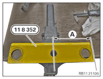
- Prepare the special tool 0 494 116 (11 8 352) from the set of special tools 0 493 997 (11 8 350) in a vice.
- Mark the special tool 0 494 116 (11 8 352) in the area (A).
(A) = 50 mm
- Set a punch in the center of the marked area.
- Drill a hole with a 8.5 mm drill.
NOTE:
RISK OF DAMAGE
Improper screw length can cause component damage.
The use of screws of improper length can lead to component damage.
Improper screw length can cause component damage.
The use of screws of improper length can lead to component damage.
- Note the correct screw length.
- Install screws that correspond to the original length.
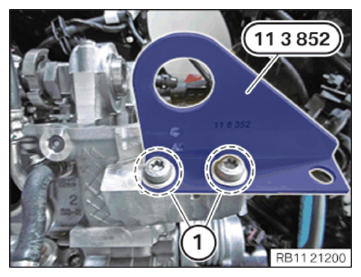
- Tighten the special tool 0 494 116 (11 8 352) from the set of special tools 0 493 997 (11 8 350) on the cylinder head with standard M8 screws (1).TIGHTENING TORQUES SPECIFICATION
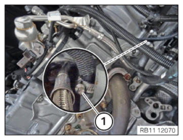
Special tool to cylinder head bank 2 M8 screw Tightening torque 25 Nm - Loosen hose clamp (1).
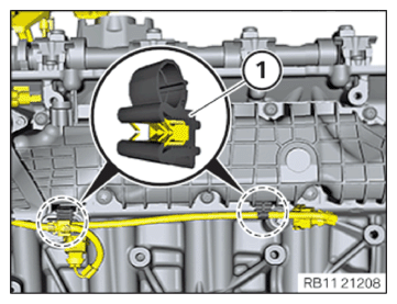
- Detach the coolant hose from the left cylinder head.NOTE: To provide a better overview: Schematic diagram with partially hidden components.
- Release the wiring harness mountings (1) below the intake system.
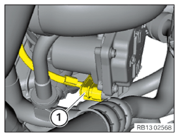
- Unlock and disconnect the plug connection (1) on the throttle valve.
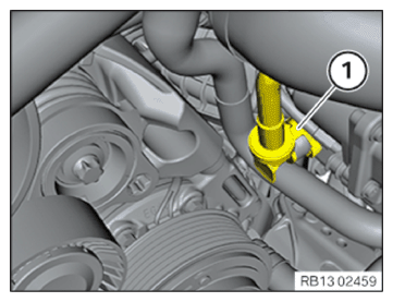
- Unlock and disconnect the quick-release coupling (1).
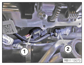
- Unlock the connector (1) and detach from the servomotor.
- Unlock the connector (2) and detach from pressure sensor on intake plenum.
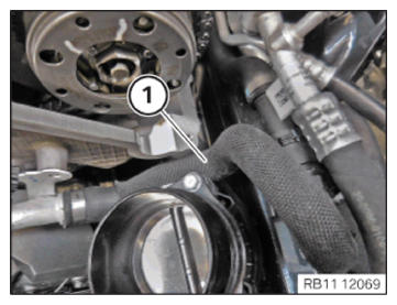
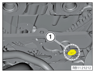
- Feed out the coolant hose (1) and set it aside.
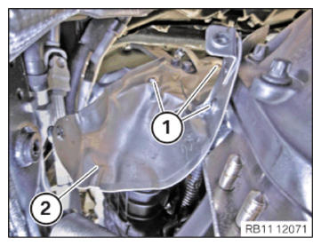
- Loosen screws (1).
- Remove the heat shield (2) at rear on the cylinder head.
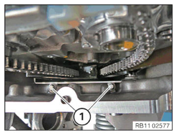
- Release the screws (1) the timing case cover.
- Release the screw of the slide rail on the cylinder head of cylinder bank (1).
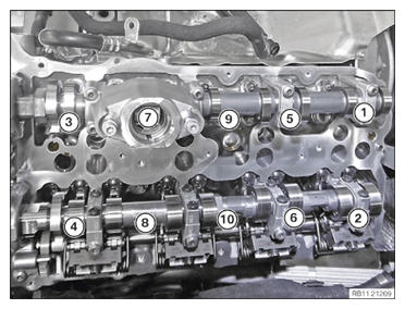
- Loosen screws (1) to (10).
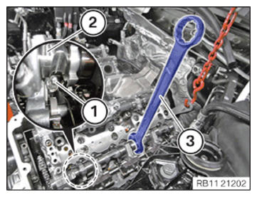
- Twist the camshaft (2) to remove the cylinder head bolt (1) on cylinder 5 with a standard open-end wrench (3) on the hexagon head.NOTE: The work must be performed with vehicle care to prevent component damage.
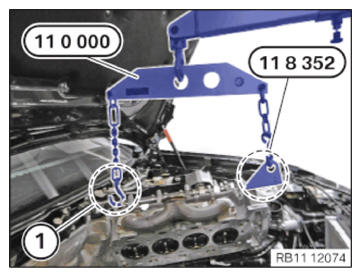
- Attach the special tool 0 490 561 (11 0 000) on the retaining tab (1) and on the special tool 0 494 116 (11 8 352) from the set of special tools 0 493 997 (11 8 350).NOTE: The work must be performed with vehicle care to prevent component damage.
- Mind the free movement of the tensioning rails and slide rails.
Risk of breakage!
- Carefully lift the cylinder head using a workshop crane.
- Carefully feed out and remove the cylinder head with a workshop crane and 3 support persons.
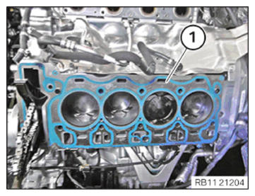
- Remove cylinder head gasket (1).