Install counterbalance shafts (B48 technical update 0/1)
- Vehicle up to production year 07/16
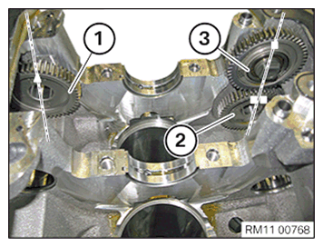
- Mount the gears (1) (2) and (3) so that the marks point vertically
up to the oil sump sealing surface (upwards).
Mark on the gear (1) on the intake side: Triangle
Mark on gear (2) on exhaust side: Two rectangles
Mark on gear (3) on exhaust side: one rectangle
- Vehicle from production year 07/16
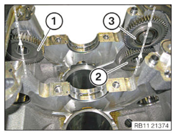
- Mount the gears (1) (2) and (3) so that the marks point vertically
up to the oil sump sealing surface (upwards).
Mark on the gear (1) on the intake side: Triangle
Mark on the gear (2) on the exhaust side: Triangle
Mark on gear (3) on exhaust side: one rectangle
- Replace the gear (1).
Parts: Gear
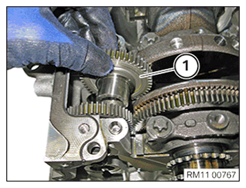
- Install the gear (1).
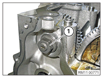
- Tighten the nut (1) hand-tight.
- Make sure that the gears are not switched.
The gear (1) is marked with an (A) and must be installed on the exhaust side.
- Replace the gear (1).
Parts: Gear
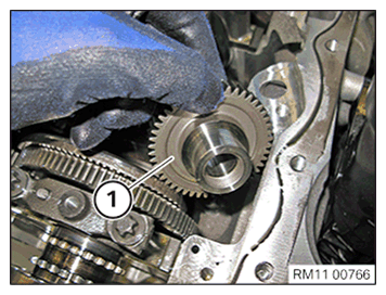
- Install the gear (1).
- Make sure that the gears are not switched.
The gear (1) is marked with an (E) and must be installed on the intake side.
- Replace the gear (1).
Parts: Gear
- Install the gear (1).
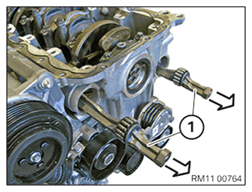
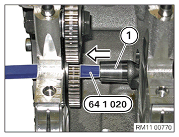
- Carefully install the counterbalance shafts (1) in the opposite direction of the arrow in the crankcase.
Do not drop the counterbalance shafts (1) into the bearing positions.
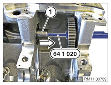
- Slide the special tool 0 493 681 (64 1 020) or another suitable tool through the gear into the counterbalance shaft.
- Carefully insert the counterbalance shaft (1) into the gear on the intake side.
- Slide the special tool 0 493 681 (64 1 020) or another suitable tool through the gear into the counterbalance shaft.
- Carefully insert the counterbalance shaft (1) into the gear on the exhaust side.
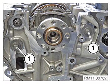
- Screw the bolts (1) into the counterbalance shafts on the left and right.
- Bolts must (1) not be tightened.
The counterbalance shafts will be positioned in the next operation.
- Rotate the crankshaft to the lower dead center of the first cylinder.
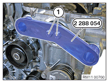
- Mount the special tool 2 288 054
and abut the bolts (1).NOTE: The description is for one component only. The procedure is identical for all further components.
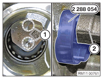
- Make sure the special tool 2 288 054 is correctly fitted in the guides (1) of the counterbalance shaft (2).
- If necessary, turn the crankshaft slightly.
- Tighten special tool 2 288 054. TIGHTENING TORQUES SPECIFICATION
Special tool 2 288 054 to crankshaft Tightening torque 20 Nm - Tighten the screws (1).TIGHTENING TORQUES SPECIFICATION
Drive wheel to counterbalance shafts Screw
Replace screws.1. Tightening torque 20 Nm 2. Angle of rotation 180° - Unscrew the bolts (1) and remove the special tool 2 288 054.
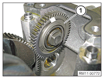
- Align the gear (1) in the direction of the arrow until it rests against the gear (2).
- Tighten nut (3).TIGHTENING TORQUES SPECIFICATION
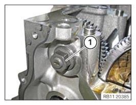
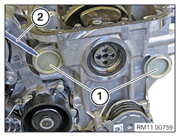
Idler gear to crankcase M12X1.5 1. Tightening torque 10 Nm 2. Angle of rotation 45° - Replace the sealing cap (1).
Parts: Sealing cap
- Make sure the O-rings of the sealing cap (1) are fitted correctly.
- Mount both sealing caps (1).
Follow-up Work
- Refer to INSTALLING THE OIL DEFLECTOR
- Refer to INSTALL THE OIL VACUUM PUMP (530e 2018-2020) , or INSTALL THE OIL VACUUM PUMP (530e xDrive 2018-2020) .
- Refer to INSTALLING THE REAR TIMING CASE COVER .
- Refer to REFITTING SUMP .
- Refer to INSTALLING THE FLYWHEEL .
- Refer to INSTALLING THE VIBRATION DAMPER .
- Refer to SEALING THE OIL DUCT .
- Refer to CLEAN SEALING SURFACES .
- Refer to REPLACE CYLINDER HEAD GASKET .
- Refer to INSTALLING THE CYLINDER HEAD .
- Refer to ATTACH THE OIL RETURN LINE FOR THE EXHAUST TURBOCHARGER .
- Refer to BLOCKING THE CAMSHAFTS
- Refer to INSTALL EXHAUST CAMSHAFT ADJUSTER .
- Refer to INSTALLING THE INTAKE ADJUSTER .
- Refer to PRELOAD TIMING CHAIN
- Refer to TIGHTENING THE VANOS CENTRAL VALVE .
- Refer to DISASSEMBLING ALL SPECIAL TOOLS
- Refer to CHECKING CAMSHAFT TIMING .
- Refer to INSTALLING THE ACOUSTIC COVER FOR THE OIL SUMP .
- Refer to INSTALLING THE THERMOSTAT ON THE TRANSMISSION OIL LINES .
- Refer to INSTALL THE CYLINDER HEAD COVER (ENGINE REMOVED)
- Refer to INSTALL FRONT ENGINE ENCAPSULATION .
- Refer to INSTALL THE COOLANT FEED LINE FOR THE EXHAUST TURBOCHARGER (COOLANT RETURN LINE REMOVED)
- Refer to INSTALL THE COOLANT RETURN LINE FOR THE EXHAUST TURBOCHARGER (AUXILIARY COOLANT PUMP REMOVED)
- Refer to INSTALLING AUXILIARY COOLANT PUMP FOR THE EXHAUST TURBOCHARGER .
- Refer to INSTALL BOTH ACTUATORS (ENGINE REMOVED)
- Refer to PREPARE FOR THE INSTALLATION OF THE HIGH PRESSURE PUMP
- Refer to INSTALL HIGH PRESSURE PUMP .
- Refer to INSTALLING FUEL DELIVERY LINE .
- Refer to PREPARE THE INJECTORS FOR INSTALLATION .
- Refer to INSTALL INJECTORS
- Refer to INSTALLING THE HIGH-PRESSURE LINE BETWEEN THE HIGH-PRESSURE PUMP AND THE HIGH-PRESSURE RAIL .
- Refer to INSTALLING THE IGNITION COILS .
- Refer to INSTALLING THE INTAKE PLENUM .
- Refer to INSTALLING THE TANK VENT VALVE .
- Refer to REMOVE ENGINE FROM ASSEMBLY STAND
- Refer to TIGHTENING THE OIL DRAIN PLUG
- Refer to TIGHTENING THE OIL FILTER CAP
- Refer to INSTALLING THE DRIVE BELT FOR THE COOLANT PUMP .
- Refer to INSTALL ENGINE .
- Refer to TOPPING UP THE MOTOR OIL