Remove cylinder head
NOTE:
DANGER
High-voltage system.
The high-voltage system operates on the basis of hazardous, electrical voltage and high currents. Danger to life through electric shock!
High-voltage system.
The high-voltage system operates on the basis of hazardous, electrical voltage and high currents. Danger to life through electric shock!
- All work on the high-voltage system may only be carried out by specially trained and technically experienced personnel.
- For additional information see:
- For additional information see:
WARNING:
Hot surfaces.
Risk of burning!
Risk of burning!
- Perform all work only on components that have cooled down.
WARNING:
Working on fuel system.
Risk of fire! Danger of explosion!
Risk of fire! Danger of explosion!
- When working on the fuel system, make sure that the workbay is sufficiently ventilated, e.g. using extraction unit.
- Tightly seal off open lines and connections; collect any escaping fuel directly at the point of exit.
- No fire, sparks, open flames or smoking.
CAUTION:
On releasing high pressure line, fuel may emerge at high speed.
Danger of injury!
Danger of injury!
- Wear suitable personal protective equipment.
- Allow the cooling system to cool down to a temperature below 40°C before starting installation work.
- Note warnings on cylinder head cover.
NOTE:
RISK OF DAMAGE
Engine damage due to lack of engine oil.
Lack of engine oil after the cylinder head or the engine has been replaceed may cause damage to the valve gear.
Engine damage due to lack of engine oil.
Lack of engine oil after the cylinder head or the engine has been replaceed may cause damage to the valve gear.
- Do not start the engine after replacing the cylinder head or the engine without following the repair notes.
- The repair notes on replacing the cylinder head or the engine must be followed!
- For additional information, see: REPAIR NOTES FOR CYLINDER HEAD OR ENGINE REPLACEMENT
NOTE:
TECHNICAL INFORMATION
After replacement of the engine or cylinder head: If necessary, reprogram/encode Digital Motor Electronics (DME).
Read out I level of the vehicle and the proceed accordingly.
It is imperative to observe Product and Measures Management Aftersales measure 62634754.
For further information, see the applicable BMW parts catalogue.
NOTE:
TECHNICAL INFORMATION
Collect and dispose of emerging fluids. Observe country-specific waste disposal regulations.
Collect and dispose of emerging fluids. Observe country-specific waste disposal regulations.
Preliminary works
- Refer to BRING FRONT COMPARTMENT LID IN THE SERVICE POSITION .
- Refer to REMOVING THE ACOUSTIC COVER .
- Refer to REMOVE THE COVER OF THE ENGINE COMPARTMENT AT THE REAR LEFT
- Refer to REMOVE THE SEAL FOR THE REAR BONNET .
- Refer to REMOVE LEFT AND RIGHT WIPER ARM .
- Refer to REMOVE COWL PANEL COVER .
- Refer to REMOVING TRAILING LINK AT SPRING STRUT DOME (LEFT-HAND) , or REMOVING TRAILING LINK AT SPRING STRUT DOME (RIGHT-HAND .
- Refer to REMOVING THE CENTER BULKHEAD UPPER PART .
- Refer to REMOVING THE SEALING FRAME ON THE RIGHT .
- Refer to LOOSENING HIGH-VOLTAGE CABLES ON THE ELECTRICAL MACHINE ELECTRONICS .
- Refer to REMOVING ACOUSTIC COVER AT REAR .
- Refer to REMOVING LEFT SEALING FRAME .
- Refer to REMOVING THE CENTER BULKHEAD LOWER SECTION
- Refer to REMOVING INTAKE SILENCER HOUSING .
- Refer to REMOVE RESONATOR .
- Refer to REMOVING CLEAN AIR PIPE .
- Refer to REMOVE CHARGE AIR LINE .
- Refer to REMOVE THE CYLINDER HEAD COVER ACOUSTIC COVER
- Refer to REMOVE IGNITION COILS .
- Refer to REMOVING ALL SPARK PLUGS .
- Refer to REMOVE THE HIGH PRESSURE LINE BETWEEN THE HIGH PRESSURE PUMP AND THE RAIL .
- Refer to REMOVE FUEL DELIVERY LINE .
- Refer to REMOVE HIGH PRESSURE PUMP .
- Refer to REMOVING INJECTORS .
- Refer to REMOVING THE HEAT SHIELD FROM THE EXHAUST MANIFOLD .
- Refer to REMOVING THE FRONT OXYGEN SENSOR .
- Refer to REMOVE MONITORING OXYGEN SENSOR .
- Refer to REMOVING THE DME CONTROL UNIT .
- Refer to REMOVE THE INTEGRATED POWER SUPPLY MODULE (PDM) .
- Refer to REMOVE CONTROL UNIT BRACKET .
- Refer to REMOVE FRONT UNDERBODY PROTECTION AND/OR FRONT STIFFENING PLATE .
- Refer to REMOVING THE UNDERBODY PROTECTION OF THE STEERING GEAR AND FRONT STIFFENING PLATE RESPECTIVELY .
- Refer to REMOVING REAR STIFFENING PLATE .
- Refer to RELEASING THE OIL DRAIN PLUG .
- Refer to TIGHTENING THE OIL DRAIN PLUG
- Refer to DRAINING THE COOLANT FROM THE HIGH-TEMPERATURE COOLING SYSTEM .
- Refer to DRAIN THE COOLANT FROM THE LOW-TEMPERATURE COOLING SYSTEM
- Refer to REMOVE THE CONNECTING SUPPORT FROM THE TUNNEL
- Refer to IF INSTALLED: REMOVING RIGHT AND LEFT TORSION STRUT .
- Refer to REMOVE THE REAR AXLE COVER .
- Refer to REMOVE COMPLETE EXHAUST SYSTEM .
- Refer to REMOVE CATALYTIC CONVERTER .
- Refer to PARTIALLY RELEASING ACOUSTIC COVER OF OIL SUMP .
- Refer to REMOVING THE THERMOSTAT FROM THE TRANSMISSION OIL LINES .
- Refer to REMOVING THE ACOUSTIC COVER FOR THE ENGINE AT THE FRONT .
- Refer to REMOVING AUXILIARY COOLANT PUMP FOR THE EXHAUST TURBOCHARGER .
- Refer to REMOVE FRONT ENGINE ENCAPSULATION .
- Refer to REMOVE THE COOLANT FEED LINE FOR THE EXHAUST TURBOCHARGER (COOLANT RETURN LINE REMOVED) .
- Refer to REMOVE THE OIL RETURN LINE FOR THE EXHAUST TURBOCHARGER .
- Refer to REMOVE THE COOLANT RETURN LINE FOR THE EXHAUST TURBOCHARGER (AUXILIARY COOLANT PUMP REMOVED) .
- Refer to REMOVE THE OIL FEED LINE FOR THE EXHAUST TURBOCHARGER (ENGINE ENCAPSULATION REMOVED) .
- Refer to REMOVE TANK VENT VALVE .
- Refer to REMOVING THE INTAKE PLENUM .
- Refer to REMOVING BOTH ACTUATORS .
- Refer to REMOVING THE CYLINDER HEAD COVER .
- Refer to TURNING THE ENGINE ON THE VIBRATION DAMPER
- Refer to BLOCKING THE CAMSHAFTS
- Refer to BLOCK THE CRANKSHAFT IN HE TDC FIRING POSITION OF CYLINDER 1 .
- Refer to REMOVING CHAIN TENSIONER .
- Refer to RELEASING THE VANOS CENTRAL VALVE (INTAKE) , or RELEASING THE VANOS CENTRAL VALVE (EXHAUST) .
- Refer to REMOVE EXHAUST CAMSHAFT ADJUSTER .
- Refer to REMOVING INTAKE ADJUSTER .
- Refer to DISASSEMBLING THE SPECIAL TOOL 2 358 122 .
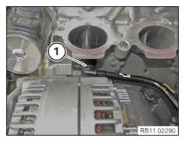
- Unlock coolant line (1) and pull off.
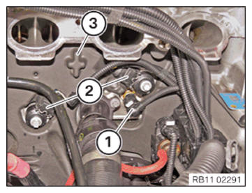
- Unlock and pull off the connectors (1) and (2).
- Loosen the engine encapsulation (3) around the cylinder head.
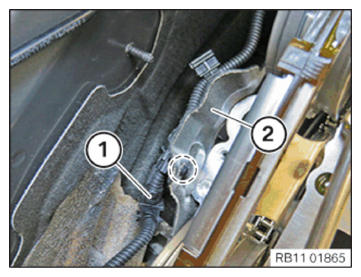
- Unclip the cable (1) from the acoustic cover (2) in the highlighted area.NOTE: The figure shows the rear side of the engine.
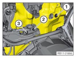
- Release the screws (1) to (3).
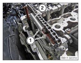
- Loosen screws (1).
- Remove the slide rail (2).
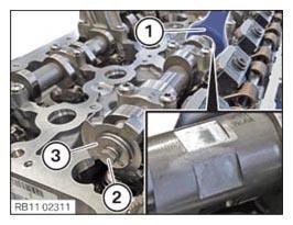
- Secure the intake camshaft with an open-end spanner (1).
- Unscrew the bolt (2) and remove the camshaft sensor wheel (3).
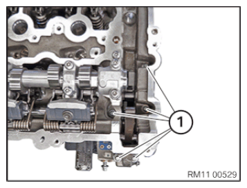
- Loosen screws (1).
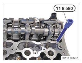
- Use the special tool 0 495 747 (11 8 580)
for releasing the cylinder head bolts.
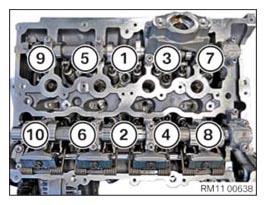
- Unscrew the cylinder head bolts in the sequence (10) to (1) in 360 degree steps.
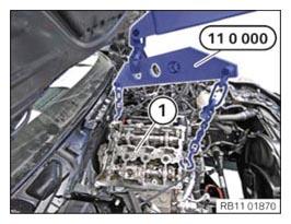
- Remove the cylinder head (1) and the exhaust turbocharger with the workshop crane and the special tool 0 490 561 (11 0 000)
.NOTE: The figure shows the engine B38.