Installing the cylinder head
NOTE:
TECHNICAL INFORMATION
After replacing the motor or cylinder head: Reprogram or encode the digital motor electronics (DME) if necessary.
Read out the vehicle I-level and proceed accordingly.
Be absolutely certain to pay attention to PuMA measure 62634754.
For further information, see the applicable BMW parts catalogue.
After replacing the motor or cylinder head: Reprogram or encode the digital motor electronics (DME) if necessary.
Read out the vehicle I-level and proceed accordingly.
Be absolutely certain to pay attention to PuMA measure 62634754.
For further information, see the applicable BMW parts catalogue.
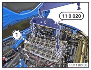
- Attach special tool 0 490 567 (11 0 020) to workshop crane.
- Install cylinder head (1) and the exhaust turbocharger with the help of a second person, using the workshop crane and the special tool 0 490 567 (11 0 020).
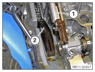
- Feed in guide rail (2) when installing the cylinder head.
- Attach timing chain through the guide rail (1).
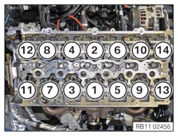
- Replace screws (1) to (14).
Parts: screw
- Tighten the screws using the special tool 0 495 747 (11 8 580) in the order (1) to (14).
- Mark the cylinder head bolts (1) to (14) with a line after reaching the jointing torque (in front of the angle of rotation).TIGHTENING TORQUES SPECIFICATION
Cylinder head to crankcase (cylinder head bolt) M11 x 188 13.9, screw head height 13 mm.
Replace screws.Joining torque 30 Nm Joining torque 50 Nm Angle of rotation 90° Angle of rotation 90° Angle of rotation 90° Angle of rotation 90° M11 x 188 11.9, screw head height 11 mm.
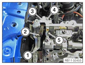
Replace screws.Joining torque 30 Nm Angle of rotation 90° Angle of rotation 90° Angle of rotation 90° - Tighten the screws (1) to (5).TIGHTENING TORQUES SPECIFICATION
Cylinder head to crankcase/timing case cover M8 x 40
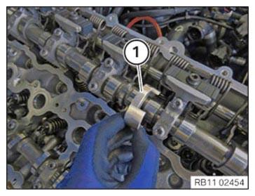
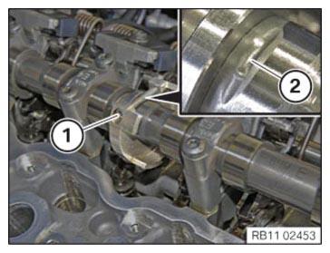
Replace screws.Tightening torque 19 Nm - Feed in camshaft sensor wheel (1) on the intake camshaft.
- Rotate intake camshaft, if necessary in the position shown.
The recess (2) must point up.
- Position camshaft sensor wheel and tighten the screws (1).TIGHTENING TORQUES SPECIFICATION
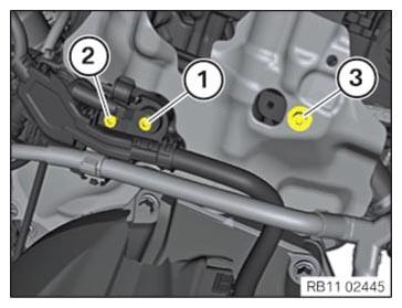
Camshaft sensor wheel to intake camshaft M4 x35 Tightening torque 4.5 Nm - Position the grounding cable and tighten the screw (2).TIGHTENING TORQUES SPECIFICATION
Grounding cable to front cylinder head M6 x 12 Tightening torque 8 Nm - Connect plug (1).
- Position the acoustic cover and tighten the screw (3).TIGHTENING TORQUES SPECIFICATION
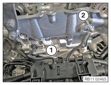
Acoustic cover, rear bottom on cylinder head M6 x 16 Tightening torque 8 Nm - Lay the wiring harness correctly and tighten the screw (2).TIGHTENING TORQUES SPECIFICATION
Cable bracket on rear cylinder head/transmission M6 x 20 Tightening torque 8 Nm - Position the grounding cable and tighten the screw (1).
TIGHTENING TORQUES SPECIFICATION
| Grounding cable on cylinder head | ||
|---|---|---|
| M6 x 16 | Tightening torque | 8 Nm |
Follow-up work
- Refer to SECURING THE OIL FEED LINE TO THE ENGINE BLOCK .
- Refer to INSTALL THE COOLANT FEED LINE (COOLANT RETURN LINE IS REMOVED) .
- Refer to INSTALL THE REAR SECTION OF THE COOLANT RETURN LINE (FRONT SECTION REMOVED) .
- Refer to INSTALL THE FRONT SECTION OF THE COOLANT RETURN LINE .
- Refer to INSTALLING THE INTAKE ADJUSTER .
- Refer to INSTALL EXHAUST CAMSHAFT ADJUSTER .
- Refer to BLOCKING THE CAMSHAFTS .
- Refer to PRELOAD TIMING CHAIN .
- Refer to TIGHTENING THE VANOS CENTRAL VALVE .
- Refer to CRANK ENGINE TWICE (AUTOMATIC TRANSMISSION) .
- Refer to DISASSEMBLING ALL SPECIAL TOOLS
- Refer to INSTALLING CYLINDER HEAD COVER .
- Refer to INSTALLING BOTH ACTUATORS .
- Refer to PREPARE THE INJECTORS FOR INSTALLATION .
- Refer to INSTALLING THE INJECTORS FOR THE CYLINDERS 4 TO 6 .
- Refer to INSTALLING THE INJECTORS FOR THE CYLINDERS 1 TO 3 .
- Refer to PREPARE FOR THE INSTALLATION OF THE HIGH PRESSURE PUMP .
- Refer to INSTALL HIGH PRESSURE PUMP .
- Refer to INSTALLING FUEL DELIVERY LINE .
- Refer to INSTALL THE HIGH-PRESSURE LINE BETWEEN THE HIGH-PRESSURE RAIL AND THE HIGH-PRESSURE PUMP .
- Refer to REPLACE SPARK PLUGS
- Refer to INSTALLING THE IGNITION COILS .
- Refer to INSTALLING THE AUXILIARY COOLANT PUMP .
- Refer to INSTALLING THE INTAKE PLENUM .
- Refer to INSTALLING THE TANK VENT VALVE .
- Refer to INSTALL FRONT ENGINE ENCAPSULATION .
- Refer to TIGHTENING THE OIL FILTER CAP .
- Refer to INSTALL CONTROL UNIT BRACKET .
- Refer to INSTALL THE INTEGRATED POWER SUPPLY MODULE (PDM) .
- Refer to INSTALLING THE DME CONTROL UNIT .
- Refer to CONNECT THE COOLANT LINES FOR THE LOW-TEMPERATURE COOLANT CIRCUIT .
- Refer to CONNECT THE COOLANT LINES FOR THE HIGH-TEMPERATURE COOLANT CIRCUIT .
- Refer to INSTALLING THE OIL RETURN LINE FOR THE EXHAUST TURBOCHARGER .
- Refer to INSTALLING THE SUPPORT FOR THE EXHAUST TURBOCHARGER .
- Refer to INSTALLING STARTER MOTOR .
- Refer to INSTALL CATALYTIC CONVERTER .
- Refer to PREPARE THE EXHAUST SYSTEM .
- Refer to INSTALLING THE COMPLETE EXHAUST SYSTEM .
- Refer to INSTALL THE CONNECTING SUPPORTS ON THE TUNNEL .
- Refer to REPLACING THE OXYGEN MONITOR SENSOR
- Refer to REPLACING THE LAMBDA OXYGEN SENSOR
- Refer to INSTALLING CENTER BULKHEAD LOWER PART
- Refer to INSTALLING THE SEALING FRAME ON LEFT AND RIGHT .
- Refer to INSTALLING ACOUSTIC COVER AT REAR .
- Refer to INSTALLING THE CENTER COWL UPPER PART .
- Refer to INSTALL TENSION STRUT ON SHOCK TOWER .
- Refer to INSTALLING WINDSHIELD PANEL COVER .
- Refer to INSTALL LEFT AND RIGHT WIPER ARM .
- Refer to INSTALL THE COVER OF THE ENGINE COMPARTMENT ON THE REAR LEFT .
- Refer to INSTALL THE FRONT HOOD SEAL AT THE REAR .
- Refer to INSTALL CHARGE AIR LINE
- Refer to INSTALL BOTTOM CLEAN AIR PIPE .
- Refer to INSTALLING THE RESONATOR WITH THE TOP CLEAN AIR PIPE .
- Refer to INSTALLING INTAKE SILENCER HOUSING .
- Refer to INSTALL FAN COWL .
- Refer to INSTALL THE REAR TOP CROSS CONNECTION .
- Refer to INSTALL FRONT CROSS CONNECTION .
- Refer to INSTALLING FRONT-END STRUT ON LEFT AND RIGHT .
- Refer to INSTALLING THE COVER ON THE LEFT AND RIGHT IN THE ENGINE COMPARTMENT AT THE TOP
- Refer to TOPPING UP THE MOTOR OIL
- Refer to FILLING THE LOW-TEMPERATURE COOLING SYSTEM WITH THE VACUUM FILLING EQUIPMENT
- Refer to FILL THE HIGH-TEMPERATURE COOLING SYSTEM WITH THE VACUUM FILLING EQUIPMENT
- Refer to CONNECTING NEGATIVE BATTERY CABLE .
- Refer to CONNECTING THE DIAGNOSTIC SYSTEM FOR POSSIBLE INTEGRATION LEVEL ENCODING AND PROGRAMMING .
- Refer to VENTING THE LOW-TEMPERATURE COOLING SYSTEM .
- Refer to VENT THE HIGH-TEMPERATURE COOLANT SYSTEM .
- Refer to INSTALL ACOUSTIC COVER .
- Refer to INSTALL THE THRUST FIELD .
- Refer to INSTALL THE FRONT UNDERBODY PROTECTION OR FRONT THRUST FIELD .
- Refer to TAKE HOOD OUT OF THE SERVICE POSITION .
- Refer to CHECK ENGINE OIL LEVEL .