Installing piston with connecting rod
NOTE:
TECHNICAL INFORMATION
Piston, piston pin, connecting rod and connecting rod bearing shells are matched to each other and balanced.
Always install the pistons, piston pins, connecting rods and connecting rod bearing shells in the cylinder from which they were removed.
Piston, piston pin, connecting rod and connecting rod bearing shells are matched to each other and balanced.
Always install the pistons, piston pins, connecting rods and connecting rod bearing shells in the cylinder from which they were removed.
NOTE:
TECHNICAL INFORMATION
The work must be performed with vehicle care to prevent component damage.
The work must be performed with vehicle care to prevent component damage.
NOTE:
The description is for one component only. The procedure is identical for all further components.
Aligning piston rings
Aligning piston rings
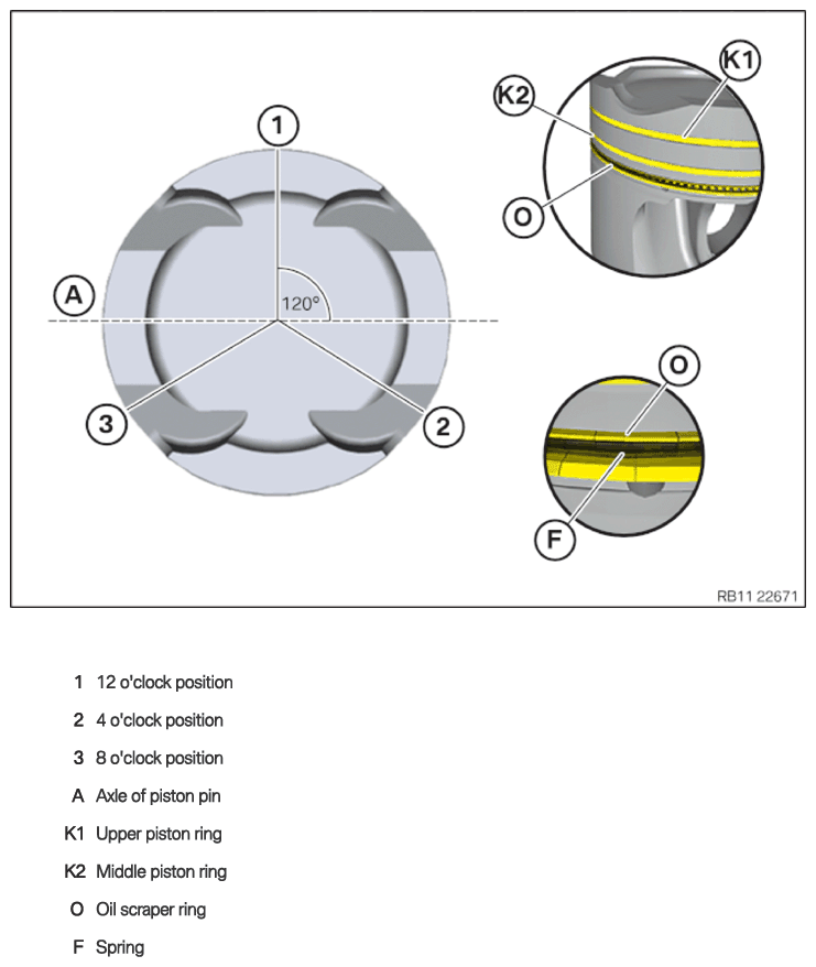
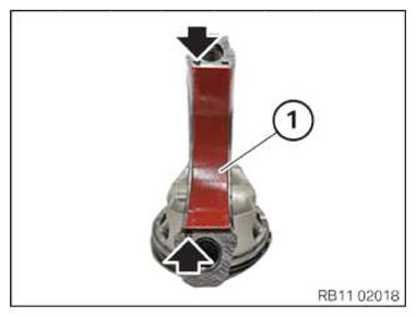
- Align the contact points of all piston rings rotated by 120° each.
Do not position contact points over axis of piston pin (A).
| Piston ring | Alignment |
|---|---|
| Lower oil scraper ring (O3) | 12 o'clock position (1) |
| Spring (O2) | 4 o'clock position (2) |
| Upper oil scraper ring (O1) | 8 o'clock position (3) |
| Central piston ring (K2) | 12 o'clock position (1) |
| Upper piston ring (K1) | 4 o'clock position (2) |
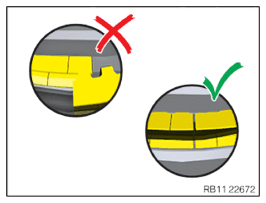
- Make sure that the contact point on the oil scraper ring does not overlap.
- For N63M3 installation is only permitted in the following combinations of connecting rod bearing shells
(1).
- Vehicles up to 03/31/2019 yellow - blue
- Vehicles up to 03/31/2019 green - red
- Vehicles up to 04/01/2019 green - red
- Vehicles up to 04/01/2019 blue - yellow
- For N63T3 installation is only permitted in the following combinations of connecting rod bearing shells
(1).
- Red - Blue
- Green - Yellow
- For S63T4 installation is only permitted in the following combinations of connecting rod bearing shells
(1).
- Green - Brown
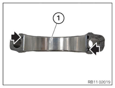
- Insert the connecting rod bearing shell (1) into the connecting rod bearing cap and secure it with the retaining lugs (see arrows).
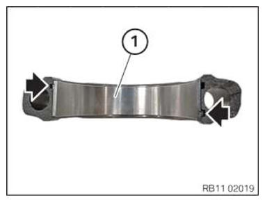
- Insert the Irox coated connecting rod bearings (1) into the connecting rod bearing cap and secure it with the retaining lugs (see arrows).
NOTE:
TECHNICAL INFORMATION
Maintain conditions of absolute cleanliness.
Maintain conditions of absolute cleanliness.
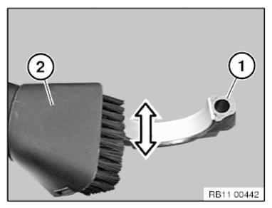
- Do not clean the crack surfaces (1) with compressed air.
- Vacuum off any new connecting rods off prior to the installation. with a commercial vacuum (2).
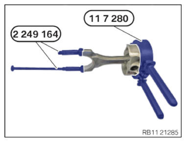
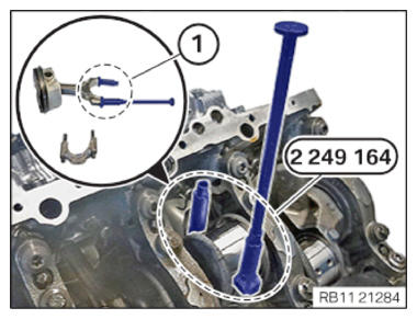
- Screw special tools 2 249 164 into the threading in area (1) of the connecting rod.
NOTE:
TECHNICAL INFORMATION
The work must be performed with vehicle care to prevent component damage.
The work must be performed with vehicle care to prevent component damage.
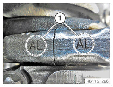
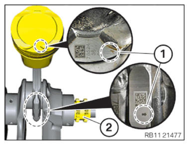
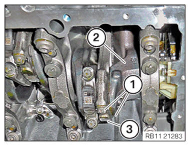
- Connecting rods and connecting rod bearing caps are denoted with the same pairing letters (1), do not mix them up.
NOTE:
RISK OF DAMAGE
Damage on the cylinder wall and oil spray nozzles.
A large force can scratch the cylinder wall and bend the oil spray nozzles.
Damage on the cylinder wall and oil spray nozzles.
A large force can scratch the cylinder wall and bend the oil spray nozzles.
- Carefully shift the piston and connecting rod in the engine block.
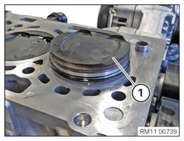
- Position the piston (1) and connecting rod at the crankcase.
- The arrows (1) on the piston and connecting rod bearing cap must point in the driving direction to the timing chain (2).
NOTE:
RISK OF DAMAGE
Damage on the cylinder wall and oil spray nozzles.
A large force can scratch the cylinder wall and bend the oil spray nozzles.
Damage on the cylinder wall and oil spray nozzles.
A large force can scratch the cylinder wall and bend the oil spray nozzles.
- Carefully shift the piston and connecting rod in the engine block.
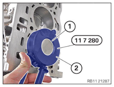
- Compress special tool 0 494 310 (11 7 280) (2) until the piston (1) can be installed into the crankcase.
Piston rings must not get caught.
Rotate crankshaft at central bolt if necessary.
- Remove special tools 2 249 164.
- Position the crankshaft (2).
NOTE:
TECHNICAL INFORMATION
The work must be performed with vehicle care to prevent component damage.
The work must be performed with vehicle care to prevent component damage.
- Insert connecting rod bearing cap so that the matching letters (3) are on the same side.
- Tighten connecting rod bolt using special tool 0 490 504 (00 9 120).
TIGHTENING TORQUES SPECIFICATION
| Connecting rod bolts, for new connecting rod | ||
|---|---|---|
| M9x1.25 Screw. Suction off crack surfaces. |
1. Joining torque | 5 Nm |
| 2. Joining torque | 20 Nm | |
| 3. Joining torque | 30 Nm | |
| 4. Angle of rotation | 75° | |
TIGHTENING TORQUES SPECIFICATION
| Screw connection, for new connecting rod bolts only | ||
|---|---|---|
| M9x1.25 Replace screws. Suction off crack surfaces. | 1. Tightening torque | 5 Nm |
| 2. Tightening torque | 20 Nm | |
| 3. Tightening torque | 30 Nm | |
| 4. Angle of rotation | 75° | |
| 5. Unscrew all bolts. | 180° | |
| 6. Tightening torque | 5 Nm | |
| 7. Tightening torque | 20 Nm | |
| 8. Tightening torque | 30 Nm | |
| 9. Angle of rotation | 75° | |
| 10. Unscrew all bolts. | 180° | |
| 11. Tightening torque | 5 Nm | |
| 12. Tightening torque | 20 Nm | |
| 13. Tightening torque | 30 Nm | |
| 14. Angle of rotation | 75° | |
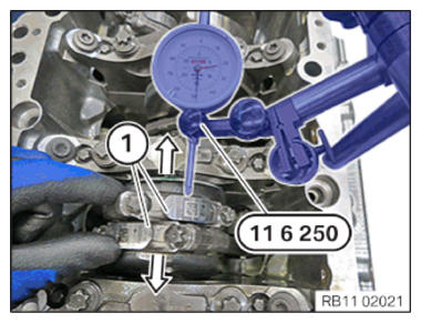
Checking the side clearance of the connecting rod bearing
- Install special tool 0 493 143 (11 6 250) on the crankcase.
- Press both connecting rods (1) up to the stop.
- Set dial gauge 0 493 143 (11 6 250) to 0.
- Press both connecting rods (1) to the stop and read out the values.
Follow-up work
- Refer to INSTALLING UPPER OIL SUMP SECTION (ENGINE REMOVED) .
- Refer to INSTALLING THE OIL FILTER ELEMENT .
- Refer to INSTALL FRONT AXLE DIFFERENTIAL
- Refer to INSTALL OIL PUMP .
- Refer to INSTALL THE LOWER OIL PAN SECTION .
- Refer to INSTALLING THE VIBRATION DAMPER .
- Refer to INSTALLING THE RIGHT CYLINDER HEAD .
- Refer to INSTALLING BOTH RIGHT VANOS ADJUSTERS .
- Refer to REMOVING THE SPECIAL TOOL TO PRETENSION THE TIMING CHAIN AT CYLINDER BANK 1 .
- Refer to INSTALLING THE HYDRAULIC CHAIN TENSIONER OF CYLINDER BANK 1 .
- Refer to INSTALL THE SEALING CAP ON THE CYLINDER HEAD OF CYLINDER BANK 1 .
- Refer to INSTALLING THE CYLINDER HEAD COVER ON THE RIGHT .
- Refer to INSTALLING VANOS SOLENOID ACTUATOR, EXHAUST OF CYLINDER BANK 1 .
- Refer to INSTALL THE VANOS SOLENOID ACTUATOR INTAKE OF CYLINDER BANK 1 .
- Refer to INSTALLING RIGHT HIGH PRESSURE PUMP .
- Refer to INSTALLING THE INJECTORS FOR THE CYLINDERS 1 TO 4 .
- Refer to INSTALLING THE RIGHT HIGH-PRESSURE RAIL .
- Refer to INSTALL IGNITION COILS OF CYLINDER BANK 1 .
- Refer to PARTIALLY INSTALLING THE GUIDE TUBE FOR THE OIL DIPSTICK .
- Refer to INSTALLING THE LEFT CYLINDER HEAD .
- Refer to INSTALLING BOTH LEFT VANOS ADJUSTERS .
- Refer to REMOVING SPECIAL TOOL TO PRETENSION TIMING CHAIN ON CYLINDER BANK 2 .
- Refer to INSTALLING THE HYDRAULIC CHAIN TENSIONER OF CYLINDER BANK 2 .
- Refer to INSTALLING THE SEALING CAP ON THE CYLINDER HEAD OF CYLINDER BANK 2 .
- Refer to INSTALLING THE LEFT CYLINDER HEAD COVER .
- Refer to INSTALLING OIL FEED LINE ON EXHAUST TURBOCHARGER CYLINDERS 5 TO 8 .
- Refer to INSTALLING VANOS SOLENOID ACTUATOR, INTAKE OF CYLINDER BANK 2 .
- Refer to INSTALL THE VANOS SOLENOID ACTUATOR EXHAUST OF CYLINDER BANK 2 .
- Refer to INSTALL THE LEFT HIGH PRESSURE PUMP .
- Refer to INSTALLING FUEL DELIVERY LINE .
- Refer to INSTALL THE IGNITION COILS OF CYLINDER BANK 2 .
- Refer to INSTALLING BOTH EXHAUST TURBOCHARGERS .
- Refer to INSTALLING FUEL DELIVERY LINE .
- Refer to INSTALLING THE IGNITION COILS OF CYLINDERS 1 AND 5 .
- Refer to INSTALLING THE CLEAN AIR PIPE OF CYLINDER BANK 2 .
- Refer to INSTALLING CLEAN AIR PIPE OF CYLINDER BANK 1 .
- Refer to INSTALLING BOTH CHARGE AIR COOLERS .
- Refer to INSTALL THE COOLANT EXPANSION TANK FOR THE LOW-TEMPERATURE COOLANT CIRCUIT (CHARGE AIR COOLER) .
- Refer to CONNECTING THE LEFT CHARGE AIR LINE TO THE EXHAUST TURBOCHARGER .
- Refer to CONNECTING THE RIGHT CHARGE AIR LINE TO THE EXHAUST TURBOCHARGER .
- Refer to INSTALLING COOLANT PUMPS .
- Refer to INSTALLING THE BELT PULLEY ON THE TORSIONAL VIBRATION DAMPER .
- Refer to INSTALLING THE BELT TENSIONER .
- Refer to INSTALL DRIVE BELT .
- Refer to REMOVING THE ENGINE FROM THE ENGINE SUPPORT BRACKET .