Remove the piston rings
CAUTION:
Component with heavy weight.
Injury hazard!
Injury hazard!
- Note component's center of gravity.
- Support component using a jack.
- Secure component against falling off the jack.
CAUTION:
On releasing high pressure line, fuel may emerge at high speed.
Injury hazard!
Injury hazard!
- Wear suitable personal protective equipment.
- Before performing any installation work, allow cooling system to cool down to less than 40°C.
- Note warnings on cylinder head cover.
NOTE:
TECHNICAL INFORMATION
Collect and dispose of emerging fluids. Observe country-specific waste disposal regulations.
Collect and dispose of emerging fluids. Observe country-specific waste disposal regulations.
Preliminary work
- Refer to REMOVE THE FRONT AXLE COMPLETELY WITH THE ENGINE AND TRANSMISSION .
- Refer to REMOVING THE ENGINE FROM THE FRONT AXLE .
- Refer to INSTALLING THE ENGINE ON THE ASSEMBLY JIG .
- Refer to REMOVING THE OIL FILLER CAP .
- Refer to RELEASING THE OIL DRAIN PLUG .
- Refer to TIGHTENING THE OIL DRAIN PLUG .
- Refer to REMOVING ACOUSTIC COVER AT REAR .
- Refer to REMOVING ALL IGNITION COILS
- Refer to REMOVING ALL SPARK PLUGS .
- Refer to REMOVING FUEL DELIVERY LINE .
- Refer to REMOVE THE HIGH PRESSURE LINE BETWEEN THE HIGH PRESSURE PUMP AND THE RAIL .
- Refer to REMOVE HIGH PRESSURE PUMP .
- Refer to REMOVING THE RAIL WITH INJECTORS OF CYLINDERS 1 TO 3 .
- Refer to REMOVING THE RAIL WITH INJECTORS OF CYLINDERS 4 TO 6 .
- Refer to REMOVING BOTH ACTUATORS .
- Refer to REMOVING THE CYLINDER HEAD COVER .
- Refer to REMOVE TANK VENT VALVE .
- Refer to REMOVING THE INTAKE PLENUM .
- Refer to REMOVING THE LAMBDA OXYGEN SENSOR .
- Refer to REMOVING THE OXYGEN SENSOR MONITOR .
- Refer to REMOVE CATALYTIC CONVERTER .
- Refer to REMOVING THE OIL RETURN LINE FOR THE EXHAUST TURBOCHARGER .
- Refer to REMOVE THE COOLANT LINE BETWEEN THE COOLANT PUMP AND CYLINDER HEAD .
- Refer to BLOCKING ENGINE IN TDC FIRING POSITION .
- Refer to REMOVING CHAIN TENSIONER .
- Refer to RELEASING THE VANOS CENTRAL VALVE OF THE INTAKE ADJUSTER .
- Refer to RELEASING VANOS CENTRAL VALVE OF THE EXHAUST CAMSHAFT ADJUSTER .
- Refer to REMOVING THE VANOS CENTRAL VALVE OF THE INTAKE ADJUSTER .
- Refer to REMOVING THE VANOS CENTRAL VALVE OF THE EXHAUST CAMSHAFT ADJUSTER .
- Refer to REMOVING INTAKE ADJUSTER .
- Refer to REMOVE EXHAUST CAMSHAFT ADJUSTER .
- Refer to REMOVE THE TEST GAUGES FOR SECURING THE CAMSHAFTS .
- Refer to REMOVING THE CYLINDER HEAD .
- Refer to REMOVING THE CYLINDER HEAD GASKET .
- Refer to REMOVE THE ACOUSTIC COVER OF THE OIL SUMP .
- Refer to REMOVING STARTER MOTOR
- Refer to REMOVE FRONT AXLE DIFFERENTIAL .
- Refer to REMOVE BEARING BRACKET .
- Refer to REMOVE OIL PAN
- Refer to REMOVE OIL VACUUM PUMP .
- Refer to REMOVING THE OIL DEFLECTOR
- Refer to REMOVING ALL PISTONS WITH CONNECTING ROD .
- Refer to MEASURING A CYLINDER .
- Refer to MEASURING ALL PISTONS .
NOTE:
RISK OF DAMAGE
Very wide spreading of the piston rings during installation/removal.
Damage to the piston rings.
Very wide spreading of the piston rings during installation/removal.
Damage to the piston rings.
- Spread the piston rings only until the piston ring can just be slid over the piston.
- Use piston ring pliers to install and remove the piston rings.
NOTE:
TECHNICAL INFORMATION
Wear safety goggles.
Wear safety goggles.
NOTE:
The description is for one component only. The procedure is identical for all further components.
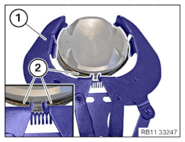
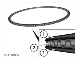
- Keep standard piston ring pliers (1) ready.
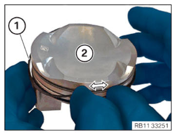
- Position the piston ring pliers (1) on the top piston ring (2).
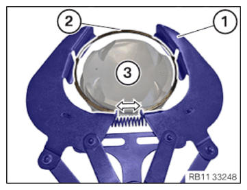
- Tension the piston ring pliers (1) in the arrow direction, feed out and remove the top piston ring (2).
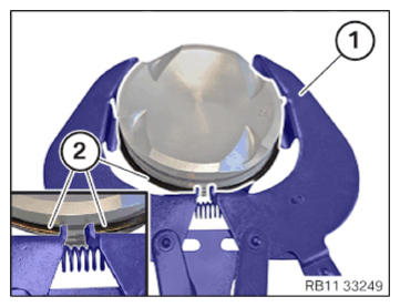
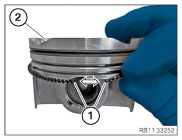
- Position the piston ring pliers (1) on the middle piston ring (2).
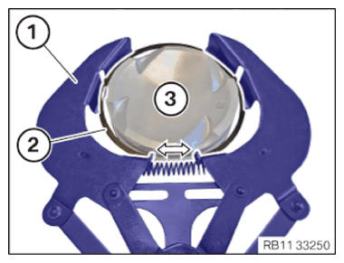
- Tension the piston ring pliers (1) in the arrow direction, feed out and remove the middle piston ring (2).
- Remove the oil scraper rings (1) and the spring (2) by hand.
- Feed out both oil scraper rings (1) in the arrow direction on the piston (2).
- Feed out and remove the spring (1) in the arrow direction on the piston (2).