Removing the cylinder head
WARNING:
Hot surfaces.
Risk of burning!
Risk of burning!
- Perform all work only on components that have cooled down.
WARNING:
Working on fuel system.
Risk of fire! Danger of explosion!
Risk of fire! Danger of explosion!
- When working on the fuel system, make sure the workstation has sufficient ventilation, e.g., by means of extraction.
- Tightly seal off open lines and connections; collect any leakage fuel directly at the point of exit.
- No fire, sparks, open flames or smoking.
CAUTION:
On releasing high pressure line, fuel may emerge at high speed.
Injury hazard!
Injury hazard!
- Wear suitable personal protective equipment.
- Before performing any installation work, allow cooling system to cool down to less than 40°C.
- Note warnings on cylinder head cover.
NOTE:
TECHNICAL INFORMATION
Collect and dispose of emerging fluids. Observe country-specific waste disposal regulations.
Collect and dispose of emerging fluids. Observe country-specific waste disposal regulations.
Preliminary work:
- Refer to BRINGING FRONT COMPARTMENT LID INTO SERVICE POSITION .
- Refer to DISCONNECTING ALL BATTERY GROUND LEADS .
- Refer to REMOVING THE ACOUSTIC COVER .
- Refer to REMOVING THE SEAL FOR THE HOOD REAR .
- Refer to REMOVING THE COVER OF THE ENGINE COMPARTMENT AT THE REAR LEFT .
- Refer to REMOVING THE COVER OF THE REAR RIGHT ENGINE COMPARTMENT .
- Refer to REMOVING LEFT AND RIGHT WIPER ARM .
- Refer to REMOVING THE COWL COVER .
- Refer to REMOVING TRAILING LINK AT SPRING BOLT .
- Refer to REMOVING THE COWL UPPER PART IN THE CENTER .
- Refer to REMOVING ACOUSTIC COVER AT REAR .
- Refer to REMOVING BOTH ACTUATORS .
- Refer to REMOVING ALL IGNITION COILS .
- Refer to REMOVING ALL SPARK PLUGS .
- Refer to REMOVING FUEL DELIVERY LINE .
- Refer to REMOVING THE HIGH PRESSURE LINE BETWEEN THE HIGH PRESSURE PUMP AND THE RAIL .
- Refer to REMOVING HIGH PRESSURE PUMP .
- Refer to REMOVING THE RAIL WITH INJECTORS OF CYLINDERS 1 TO 3 .
- Refer to REMOVING THE RAIL WITH INJECTORS OF CYLINDERS 4 TO 6 .
- Refer to REMOVING THE CYLINDER HEAD COVER (RWD) or REMOVING THE CYLINDER HEAD COVER (AWD) .
- Refer to REMOVING THE COVER ON LEFT AND RIGHT IN THE ENGINE COMPARTMENT AT THE TOP .
- Refer to REMOVING BOTH FRONT-END STRUTS .
- Refer to REMOVING FRONT CROSS CONNECTION .
- Refer to REMOVING THE REAR TOP CROSS CONNECTION .
- Refer to REMOVING THE FAN COWL .
- Refer to REMOVING THE INTAKE FILTER HOUSING (TENSION STRUT ON SHOCK TOWER REMOVED) .
- Refer to REMOVING THE RESONATOR WITH THE TOP CLEAN AIR PIPE .
- Refer to REMOVING BOTTOM CLEAN AIR PIPE .
- Refer to REMOVING CHARGE AIR LINE .
- Refer to REMOVING THE HOLDER OF THE POSITIVE BATTERY CABLE .
- Refer to REMOVING THE LAMBDA OXYGEN SENSOR .
- Refer to REMOVING THE OXYGEN SENSOR MONITOR .
- Refer to REMOVING THE DME CONTROL UNIT (2017-2020) or REMOVING THE DME CONTROL UNIT (2021-2022) .
- Refer to REMOVING THE INTEGRATED POWER SUPPLY MODULE (PDM) (2017-2020) or REMOVING THE INTEGRATED POWER SUPPLY MODULE (PDM) (2021-2022) .
- Refer to REMOVING CONTROL UNIT BRACKET (2017-2020) or REMOVING CONTROL UNIT BRACKET (2021-2022) .
- Refer to REMOVING THE FRONT UNDERBODY PROTECTION OR FRONT THRUST FIELD .
- Refer to REMOVING THE UNDERBODY PROTECTION OF THE STEERING GEAR AND THRUST FIELD RESPECTIVELY .
- Refer to REMOVING THE STIFFENING PLATE .
- Refer to REMOVING REAR UNDERBODY PROTECTION .
- Refer to REMOVING THE COVER OF THE STEERING ASSEMBLY .
- Refer to REMOVING THE CONNECTING SUPPORT FROM THE TUNNEL .
- Refer to IF INSTALLED: REMOVE THE TORSION STRUT ON THE RIGHT AND LEFT WHERE REQUIRED .
- Refer to REMOVING COMPLETE EXHAUST SYSTEM .
- Refer to REMOVING CATALYTIC CONVERTER .
- Refer to REMOVING THE OIL RETURN LINE FOR THE EXHAUST TURBOCHARGER (540i 2017-2022) , REMOVING THE OIL RETURN LINE FOR THE EXHAUST TURBOCHARGER (540i xDrive 2017-2020) , or REMOVING THE OIL RETURN LINE FOR THE EXHAUST TURBOCHARGER (540i xDrive 2021-2022) .
- Refer to DRAINING THE COOLANT FROM THE HIGH-TEMPERATURE COOLING SYSTEM .
- Refer to DRAINING THE COOLANT FROM THE LOW-TEMPERATURE COOLING SYSTEM .
- Refer to CONNECTING THE COOLANT LINES FOR THE HIGH-TEMPERATURE COOLANT CIRCUIT .
- Refer to CONNECTING THE COOLANT LINES FOR THE LOW-TEMPERATURE COOLANT CIRCUIT .
- Refer to REMOVING TANK VENT VALVE .
- Refer to REMOVING THE INTAKE PLENUM .
- Refer to REMOVING THE COOLANT LINE BETWEEN THE COOLANT PUMP AND CYLINDER HEAD .
- Refer to BLOCKING ENGINE IN TDC FIRING POSITION .
- Refer to REMOVING CHAIN TENSIONER .
- Refer to RELEASING THE VANOS CENTRAL VALVE OF THE INTAKE ADJUSTER .
- Refer to RELEASING VANOS CENTRAL VALVE OF THE EXHAUST CAMSHAFT ADJUSTER .
- Refer to REMOVING THE VANOS CENTRAL VALVE OF THE INTAKE ADJUSTER .
- Refer to RELEASING VANOS CENTRAL VALVE OF THE EXHAUST CAMSHAFT ADJUSTER .
- Refer to REMOVING INTAKE ADJUSTER .
- Refer to REMOVING EXHAUST CAMSHAFT ADJUSTER .
- Refer to REMOVING THE TEST GAUGES FOR SECURING THE CAMSHAFTS .
CAUTION:
Heavy component.
Heavy components can lead to injury or damage.
Heavy components can lead to injury or damage.
- Remove and install heavy components with the aid of another person/other persons.
NOTE:
TECHNICAL INFORMATION
Collect and dispose of emerging fluids. Observe country-specific waste disposal regulations.
Collect and dispose of emerging fluids. Observe country-specific waste disposal regulations.
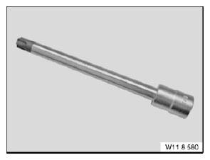
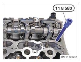
- Prepare special tool 0 495 747 (11 8 580).
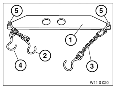
- Prepare special tool 0 490 567 (11 0 020).
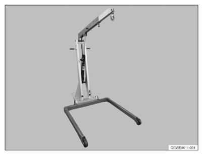
- Prepare the workshop crane 2 220 718.
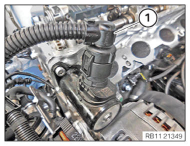
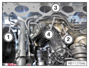
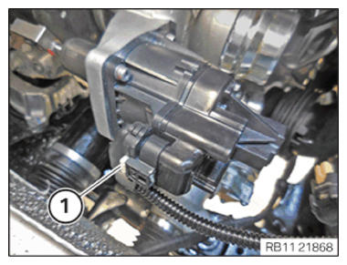
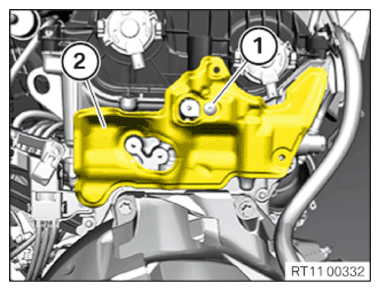
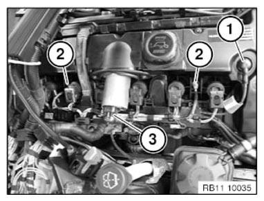
- Unlock plug connection (1) and disconnect.
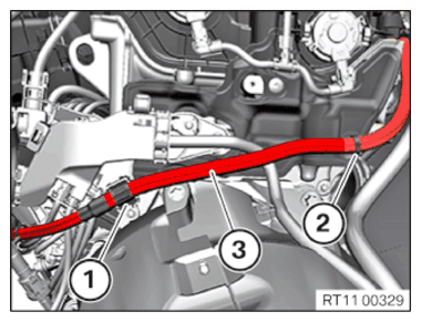
- Unlock and loosen coolant line (1).
- Catch and dispose of leakage coolant.
- Unlock plug connection (2) and disconnect.
- Loosen clamps (3).
- Guide out the wiring harness section (4) for the sensor system 1
and set side.
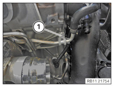
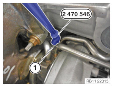
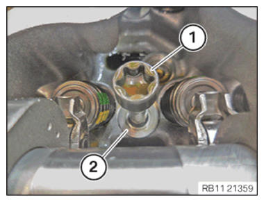
- Loosen screw (1).
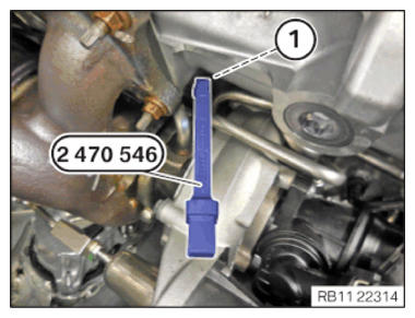
- Position special tool 2 470 546
on the screw (1).
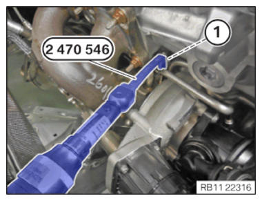
- Release the screw (1) using the special tool 2 470 546
- Feed out the screw (1) using special tool 2 470 546
and remove.
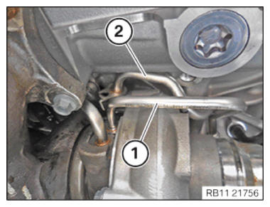
- Feed out the coolant return line (2) for the exhaust turbocharger and set it aside.
- Feed out the oil feed line (1) for the exhaust turbocharger and set it aside.
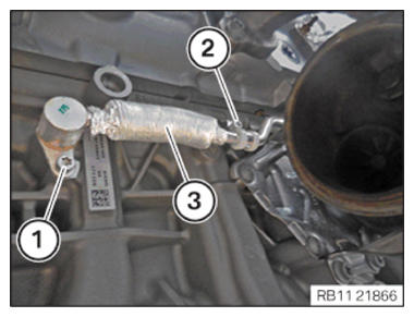
- Loosen screws (1) and (2).
- Feed the coolant feed line for the exhaust turbocharger (3) out of the crankcase and place aside.
- Catch and dispose of leakage coolant.
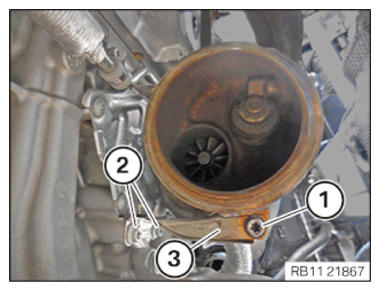
- Loosen screws (1) and (2).
- Feed out the support (3) and remove it.
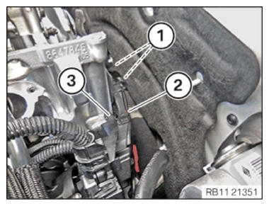
- Unlock plug connection (1) and disconnect.
- Unlock and release the clamps (1) and (2).
- Thread out positive battery cable (3) and set it aside.
- Loosen screws (1).
- Feed out the transmission wiring harness (2) on the wiring harness section (3) for sensor system 1 and place to one side.
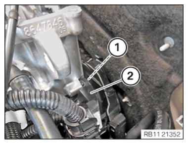
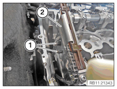
- Loosen screw (1).
- Feed out the wiring harness section (2) for sensor system 1 and place to one side.NOTE: The figure shows the rear of the engine.
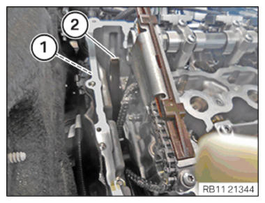
- Loosen screw (1).
- Guide out and remove the cover (2).
- Loosen screws (1).
- Guide out and remove slide rail (2).
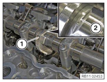
- Unscrew the bearing journal (1) from the guide rail (2).
- Rotate intake camshaft, if necessary in the position shown.
The recess (2) must point up.
- Loosen screw (1).
- Shift the camshaft sensor wheel (1) in direction of cylinder 1 and feed out from the intake camshaft.
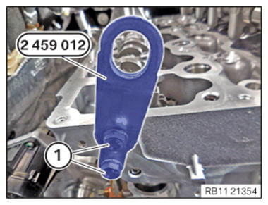
- Insert and position the special tool 2 459 012 at the cylinder head.
- Tighten the screws (1) of the special tool 2 459 012. TIGHTENING TORQUES SPECIFICATION
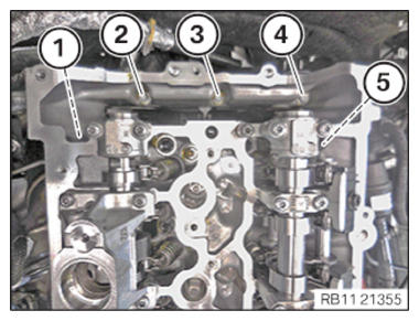
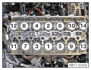
Special tool to cylinder head M8 Tightening torque: 21.5 Nm - Loosen the cylinder head bolts in the sequence from (5) to (1).
- Loosen the cylinder head bolts with the special tool 0 495 747 (11 8 580).
- Undo the screws using the special tool 0 495 747 (11 8 580) in the order (14) to (1).
- Feed out and remove all the cylinder head bolts (1).
- Feed out and remove all the washers (2).CAUTION: Heavy component.
Heavy components can lead to injury or damage.- Remove and install heavy components with the aid of another person/other persons.
NOTE: RISK OF DAMAGE
Damage to guide rails.
The application of great force can damage the guide rails of the timing chain.- When removing and installing the cylinder head, make sure that the cylinder head does not damage the guide rail.
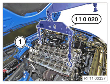
- Attach special tool 0 490 567 (11 0 020) to workshop crane.
- Lift out the cylinder head (1) and the exhaust turbocharger with the help of a second person, using the workshop crane and the special tool 0 490 567 (11 0020).