Replace all connecting rod bearing shells
CAUTION:
Component with heavy weight.
Danger of injury!
Danger of injury!
- Note component's center of gravity.
- Support component using a jack.
- Secure component against falling off the jack.
CAUTION:
On releasing high pressure line, fuel may emerge at high speed.
Danger of injury!
Danger of injury!
- Wear suitable personal protective equipment.
- Allow the cooling system to cool down to a temperature below 40°C before starting installation work.
- Note warnings on cylinder head cover.
NOTE:
TECHNICAL INFORMATION
Collect and dispose of emerging fluids. Observe country-specific waste disposal regulations.
Collect and dispose of emerging fluids. Observe country-specific waste disposal regulations.
Preliminary works
- Refer to REMOVING ENGINE .
- Refer to INSTALLING THE ENGINE ON THE ASSEMBLY STAND
- Refer to RELEASING THE OIL DRAIN PLUG .
- Refer to TIGHTENING THE OIL DRAIN PLUG .
- Refer to REMOVING ALL SPARK PLUGS .
- Refer to REMOVE THE HIGH PRESSURE LINE BETWEEN THE HIGH PRESSURE PUMP AND THE RAIL .
- Refer to REMOVE HIGH PRESSURE PUMP .
- Refer to REMOVING THE RAIL WITH INJECTORS .
- Refer to REMOVING BOTH ACTUATORS .
- Refer to REMOVING THE CYLINDER HEAD COVER .
- Refer to REMOVE TANK VENT VALVE .
- Refer to REMOVING THE INTAKE PLENUM .
- Refer to REMOVE THE HEAT SHIELD AT THE CYLINDER HEAD
- Refer to REMOVING THE OIL RETURN LINE FOR THE EXHAUST TURBOCHARGER .
- Refer to REMOVE THE COOLANT RETURN LINE FOR THE EXHAUST TURBOCHARGER .
- Refer to REMOVE THE COOLANT FEED LINE FOR THE EXHAUST GAS TURBOCHARGER .
- Refer to BLOCKING ENGINE IN THE TDC FIRING POSITION .
- Refer to REMOVING CHAIN TENSIONER .
- Refer to RELEASING THE VANOS CENTRAL VALVE OF THE INTAKE ADJUSTER .
- Refer to RELEASING VANOS CENTRAL VALVE OF THE EXHAUST CAMSHAFT ADJUSTER .
- Refer to REMOVING THE VANOS CENTRAL VALVE OF THE INTAKE ADJUSTER .
- Refer to REMOVING THE VANOS CENTRAL VALVE OF THE EXHAUST CAMSHAFT ADJUSTER .
- Refer to REMOVING INTAKE ADJUSTER .
- Refer to REMOVE EXHAUST CAMSHAFT ADJUSTER .
- Refer to REMOVE THE TEST GAUGES TO FIX THE CAMSHAFTS .
- Refer to REMOVING THE CYLINDER HEAD .
- Refer to REMOVING THE CYLINDER HEAD GASKET .
- Refer to REMOVING THE ACOUSTIC COVER OF THE OIL SUMP .
- Refer to REMOVING FLYWHEEL .
- Refer to REMOVE FRONT AXLE DIFFERENTIAL .
- Refer to REMOVE BEARING SUPPORT .
- Refer to REMOVE OIL PAN
- Refer to REMOVE THE OIL VACUUM PUMP .
- Refer to REMOVING THE OIL DEFLECTOR
- Refer to REMOVING ALL PISTONS WITH CONNECTING ROD .
NOTE:
RISK OF DAMAGE
Engine damage caused by incorrectly installed bearing shells and bearing supports.
Engine damage may result from incorrectly installing bearing shells and bearing supports.
Engine damage caused by incorrectly installed bearing shells and bearing supports.
Engine damage may result from incorrectly installing bearing shells and bearing supports.
- Always install all bearing shells and bearing supports in the same position from which they were removed.
NOTE:
TECHNICAL INFORMATION
Piston, gudgeon pin, connecting rod and connecting rod bearing shells are matched to each other and balanced.
Always install the piston, gudgeon pin, connecting rod and connecting rod bearing shells in the cylinder from which they were removed.
Piston, gudgeon pin, connecting rod and connecting rod bearing shells are matched to each other and balanced.
Always install the piston, gudgeon pin, connecting rod and connecting rod bearing shells in the cylinder from which they were removed.
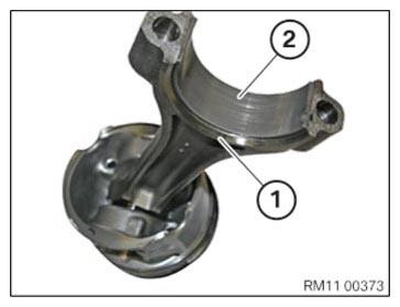
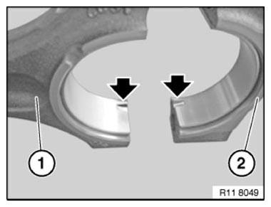
- Thread out and remove connecting rod bearing shell (2) from the connecting rod (1).
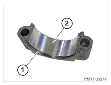
- Feed out the connecting rod bearing shell (2) from the connecting rod bearing cap (1) and remove it.
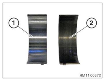
- Take note of different versions of the connecting rod bearing shells (1) and (2).
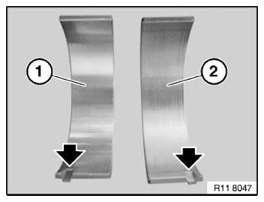
- To avoid incorrect assembly: Pay attention to marks (arrows).
The connecting rod bearing shell (1) and the connecting rod bearing shell (2) are equipped with a fuse each to act against incorrect assembly.
- To avoid incorrect assembly: Pay attention to marks (arrows).
The connecting rod bearing cap (2) and the connecting rod (1) are equipped with a fuse each to act against incorrect assembly.
- Replace the connecting rod bearing shell (2) and insert in the connecting rod (1).
Parts : Connecting rod bearing shell
- Oil the connecting rod bearing shell (2).
- Replace the connecting rod bearing shell (2) and insert into the connecting rod bearing cap (1).
Parts : Connecting rod bearing shell
- Oil the connecting rod bearing shell (2).
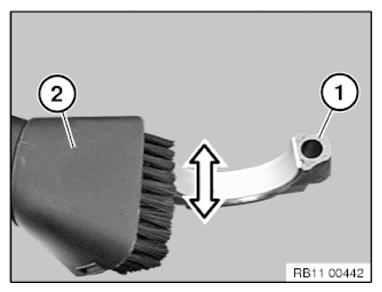
- Vacuum the crack surfaces (1) with a conventional vacuum cleaner (2).
Do not blow off the crack surfaces (1) using compressed air.
Follow-up Work
- Refer to MEASURING PISTON .
- Refer to MEASURING A CYLINDER .
- Refer to INSTALLING ALL PISTONS WITH CONNECTING ROD .
- Refer to INSTALLING THE OIL DEFLECTOR
- Refer to PREPARING THE OIL VACUUM PUMP .
- Refer to INSTALL THE OIL VACUUM PUMP .
- Refer to REFITTING SUMP .
- Refer to INSTALL BEARING SUPPORT
- Refer to INSTALL FRONT AXLE DIFFERENTIAL
- Refer to INSTALLING THE FLYWHEEL .
- Refer to INSTALLING THE ACOUSTIC COVER FOR THE OIL SUMP .
- Refer to BLOCKING THE CRANKSHAFT IN THE TDC FIRING POSITION OF CYLINDER 1 .
- Refer to SEAL THE OIL DUCT .
- Refer to CLEAN SEALING SURFACES .
- Refer to REPLACE CYLINDER HEAD GASKET .
- Refer to INSTALLING THE CYLINDER HEAD .
- Refer to ADJUST THE CAMSHAFTS WITH THE SPECIAL TOOL .
- Refer to INSTALL EXHAUST CAMSHAFT ADJUSTER .
- Refer to INSTALLING THE INTAKE ADJUSTER .
- Refer to INSTALL THE VANOS CENTRAL VALVE OF THE INTAKE ADJUSTER .
- Refer to INSTALLING THE VANOS CENTRAL VALVE OF THE EXHAUST CAMSHAFT ADJUSTER .
- Refer to PRETENSION THE TIMING CHAIN WITH THE SPECIAL TOOL .
- Refer to TIGHTENING THE VANOS CENTRAL VALVE OF THE EXHAUST CAMSHAFT ADJUSTER .
- Refer to TIGHTENING THE VANOS CENTRAL VALVE OF THE INTAKE ADJUSTER .
- Refer to DISASSEMBLING ALL SPECIAL TOOLS
- Refer to INSTALL CHAIN TENSIONER .
- Refer to CHECKING CAMSHAFT TIMING .
- Refer to INSTALLING THE OIL RETURN LINE FOR THE EXHAUST TURBOCHARGER .
- Refer to INSTALL THE COOLANT RETURN LINE FOR THE EXHAUST TURBOCHARGER .
- Refer to INSTALL COOLANT LINE BETWEEN THE COOLANT PUMP AND CYLINDER HEAD .
- Refer to INSTALL THE HEAT SHIELD ON THE CYLINDER HEAD
- Refer to INSTALLING CYLINDER HEAD COVER .
- Refer to INSTALLING BOTH ACTUATORS .
- Refer to PREPARE THE INJECTORS FOR INSTALLATION .
- Refer to INSTALLING THE RAIL WITH INJECTORS .
- Refer to INSTALLING THE HIGH PRESSURE PUMP .
- Refer to INSTALLING HIGH PRESSURE LINE BETWEEN RAIL AND HIGH PRESSURE PUMP .
- Refer to INSTALLING ALL SPARK PLUGS .
- Refer to INSTALLING THE INTAKE PLENUM .
- Refer to INSTALLING THE TANK VENT VALVE .
- Refer to TOPPING UP THE ENGINE OIL .
- Refer to CHECK/ADD FRONT AXLE TRANSMISSION OIL .
- Refer to REMOVING THE ENGINE FROM THE ASSEMBLY STAND
- Refer to INSTALL ENGINE .