Remove the sealing cap on the cylinder head of the cylinder bank 1
WARNING:
Hot surfaces.
Risk of burning!
Risk of burning!
- Perform all work only on components that have cooled down.
WARNING:
Vehicle may slip off the vehicle hoist if the vehicle hoist is handled incorrectly.
Danger! Immobilization period-threatening injuries!
Danger! Immobilization period-threatening injuries!
- Observe safety instructions on raising the vehicle using a vehicle hoist.
- For additional information see: RAISE THE VEHICLE USING A VEHICLE LIFT .
WARNING:
Working on 12 V electrical system.
Risk of short circuits! Risk of fire!
Risk of short circuits! Risk of fire!
- Make sure that there is no charger connected to the jump start terminal in the engine compartment.
- Detach battery ground lead from battery.
- For auxiliary batteries: Detach battery minus cables from all auxiliary batteries.
WARNING:
Working on fuel system.
Risk of fire! Danger of explosion!
Risk of fire! Danger of explosion!
- When working on the fuel system, make sure the workstation has sufficient ventilation, e.g., by means of extraction.
- Tightly seal off open lines and connections; collect any leakage fuel directly at the point of exit.
- No fire, sparks, open flames or smoking.
NOTE:
RISK OF DAMAGE
Careless handling of tools and sharp-edged components.
Scratches, surface damage.
Careless handling of tools and sharp-edged components.
Scratches, surface damage.
- Protect working area.
- Handle tools and components carefully.
NOTE:
TECHNICAL INFORMATION
Collect and dispose of emerging fluids. Observe country-specific waste disposal regulations.
Collect and dispose of emerging fluids. Observe country-specific waste disposal regulations.
NOTE:
TECHNICAL INFORMATION
When the engine is stopped after the completion of trip, it may be necessary to run the electric fan. In rare cases, operation of the electric fan can last up to 11 min. This protects the components. In this case, replacing the electric fan will not remedy the problem!
When the engine is stopped after the completion of trip, it may be necessary to run the electric fan. In rare cases, operation of the electric fan can last up to 11 min. This protects the components. In this case, replacing the electric fan will not remedy the problem!
Preliminary work
- Refer to DISCONNECTING ALL BATTERY GROUND LEADS .
- Refer to REMOVING THE CONNECTING SUPPORT FROM THE TUNNEL .
- Refer to REMOVING CENTER REAR UNDERSHIELD .
- Refer to REMOVING EXHAUST SYSTEM .
- Refer to REMOVING THE RETAINING BRIDGE .
- Refer to REMOVING THE RETAINING BRIDGE IN VEHICLES WITH A GASOLINE PARTICULATE FILTER .
- Refer to PARTIALLY REMOVING THE LEFT LAMBDA OXYGEN SENSOR .
- Refer to PARTIALLY REMOVING THE LAMBDA OXYGEN SENSOR .
- Refer to REMOVING THE LEFT OXYGEN SENSOR MONITOR .
- Refer to REMOVING THE RIGHT OXYGEN SENSOR MONITOR .
- Refer to REMOVING UPPER HEAT SHIELD .
- Refer to REMOVING THE LEFT HEAT SHIELD .
- Refer to REMOVING RIGHT HEAT SHIELD .
- Refer to REMOVING THE COVER OF THE REAR RIGHT ENGINE COMPARTMENT .
- Refer to REMOVING THE COVER OF THE ENGINE COMPARTMENT AT THE REAR LEFT .
- Refer to REMOVING LEFT AND RIGHT WIPER ARM .
- Refer to REMOVING THE COWL COVER .
- Refer to REMOVING TRAILING LINK AT SPRING BOLT .
- Refer to REMOVING THE COWL UPPER PART IN THE CENTER .
- Refer to LIFTING THE HEAT SHIELD .
- Refer to REMOVING THE CATALYTIC CONVERTER FOR CYLINDERS 1 TO 4 .
- Refer to REMOVING THE COVER ON LEFT AND RIGHT IN THE ENGINE COMPARTMENT AT THE TOP .
- Refer to REMOVING LEFT INTAKE FILTER HOUSING WITH LEFT FRONT-END STRUT .
- Refer to REMOVING RIGHT INTAKE FILTER HOUSING WITH RIGHT FRONT-END STRUT .
- Refer to REMOVING FRONT CROSS CONNECTION .
- Refer to REMOVING THE REAR TOP CROSS CONNECTION .
- Refer to REMOVING FAN COWL .
- Refer to REMOVING DRIVE BELT .
- Refer to RELEASING LEFT CHARGE AIR LINE PARTIALLY .
- Refer to PARTIALLY RELEASING THE RIGHT CHARGE AIR LINE .
- Refer to REMOVING THE FRONT RIGHT LOWER WHEEL ARCH COVER .
- Refer to REMOVING THE LEFT FRONT BOTTOM WHEEL ARCH COVER .
- Refer to REMOVING THE FRONT UNDERBODY PROTECTION OR FRONT THRUST FIELD .
- Refer to REMOVING THE UNDERBODY PROTECTION OF THE STEERING GEAR AND THRUST FIELD RESPECTIVELY .
- Refer to DRAINING COOLANT .
- Refer to DRAINING THE COOLANT FOR THE LOW-TEMPERATURE COOLANT CIRCUIT .
- Refer to REMOVING THE COOLANT EXPANSION TANK FOR THE LOW-TEMPERATURE COOLANT CIRCUIT (CHARGE AIR COOLER) .
- Refer to REMOVING BOTH CHARGE AIR COOLERS .
- Refer to REMOVING THE CLEAN AIR PIPE OF CYLINDER BANK 1 .
- Refer to REMOVING THE CLEAN AIR PIPE OF CYLINDER BANK 2 .
- Refer to REMOVING THE IGNITION COILS OF CYLINDERS 1 AND 5 .
- Refer to REMOVING IGNITION COIL OF CYLINDER BANK 1 .
- Refer to REMOVING FUEL DELIVERY LINE .
- Refer to REMOVING RIGHT HIGH-PRESSURE PUMP .
- Refer to REMOVING RIGHT RAIL .
- Refer to REMOVING THE INJECTORS FOR CYLINDERS 1 TO 4 .
- Refer to REMOVING THE EXHAUST TURBOCHARGER FOR THE CYLINDERS 1 TO 4 .
- Refer to PARTIALLY RELEASING THE GUIDE TUBE FOR THE OIL DIPSTICK .
- Refer to REMOVING VANOS SOLENOID ACTUATOR, EXHAUST OF CYLINDER BANK 1 .
- Refer to REMOVING THE VANOS SOLENOID ACTUATOR INTAKE OF CYLINDER BANK 1 .
- Refer to REMOVING RIGHT CYLINDER HEAD COVER .
- Refer to REMOVING GUIDE TUBE FOR OIL DIPSTICK .
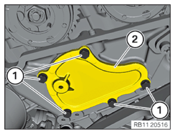
- Loosen screws (1).
- Remove the sealing cap (2) on the cylinder head.