Installing the rear timing case cover
Further information is available.
NOTE:
TECHNICAL INFORMATION
The sealing surfaces must be free of oil, grease and cleaning agents.
The sealing surfaces must be free of oil, grease and cleaning agents.
NOTE:
RISK OF DAMAGE
Damage to the surface.
The use of metal-cutting tools (e.g., emery cloths) for cleaning surfaces can damage them and lead to leaks and/or engine damage.
Damage to the surface.
The use of metal-cutting tools (e.g., emery cloths) for cleaning surfaces can damage them and lead to leaks and/or engine damage.
- Do not use any metal-cutting tools.
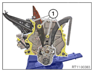
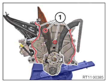
- Clean sealing surfaces (1) with special tool 0 495 102 (11 4 470).
- Clean the sealing surface (1) with the brake cleaner.CONSUMABLE - BRAKE CLEANER DESCRIPTION
Brake cleaner 2.0 500 ml, Spray can 83192365214 20, Canister 83192365215 NOTE: RISK OF DAMAGE
Damage to the surface.
The use of metal-cutting tools (e.g., emery cloths) for cleaning surfaces can damage them and lead to leaks and/or engine damage.- Do not use any metal-cutting tools.
NOTE: TECHNICAL INFORMATION
The sealing surfaces must be free of oil, grease and cleaning agents. - Clean sealing surfaces (1) with special tool 0 495 102 (11 4470).
- Clean the sealing surface (1) with the brake cleaner.CONSUMABLE - BRAKE CLEANER DESCRIPTION
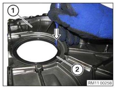
Brake cleaner 2.0 500 ml, Spray can 83192365214 20, Canister 83192365215 - Position the timing case cover (1) underneath.
- Position punch on inner side of crankshaft seal (2).
- Remove crankshaft sealing ring (2) in direction of arrow outward.
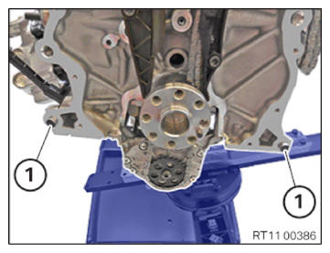
- Check the fitting sleeves (1) for damage, replace if necessary.
- Check for correct fit of fitting sleeves (1).
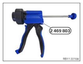
- Have the special tool 2 469 803
ready.NOTE: TECHNICAL INFORMATION
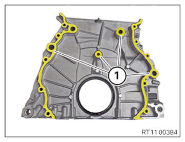
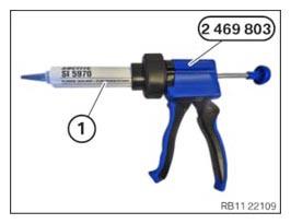
For additional information see: OVERVIEW OF CONSUMABLES (BMW PARTS CATALOGUE) - Position the sealing compound (1) as shown on the special tool 2 469 803.
Parts: Sealing compound
NOTE: TECHNICAL INFORMATION
The processing time of the liquid sealing compound can be at a maximum of 10 min.
Commissioning of the assembly is not possible until 25 minutes after the processing time.
Non-observance can lead to leaks in the assembly. - Apply the sealing compound in area (1) along the inner edge.SEALING COMPOUND DESCRIPTION
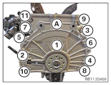
Loctite 5970 liquid sealing compound Processing time <10 minutes at room temperature 50 ml, Cartridge 83190404517 TECHNICAL DATA - HEIGHT OF SEALING BEAD SPECIFICATIONHeight of the sealing bead 2.0 mm... 2.5 mm - Replace screws (1) to (11).
Parts: Screws
- Carefully mount the timing case cover (A).
- Tighten the screws in sequence (1) to (11) with the special tool 0 490 504 (00 9 120). TIGHTENING TORQUES SPECIFICATION
Rear timing case cover on crankcase M6x31
Replace screws.Joining torque
Angle of rotation8 Nm
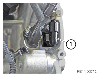
90° - Connect connectors (1) and lock.
The connector (1) must engage audibly.
- Installing the rear crankshaft seal
NOTE: TECHNICAL INFORMATION
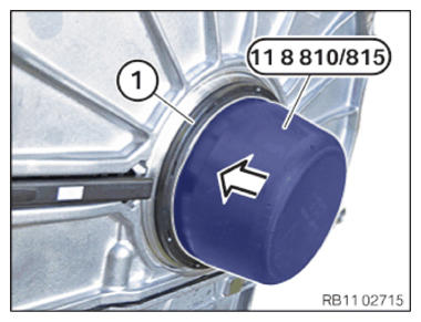
The radial shaft seal must be installed dry. Do not use motor oil or lubricant. - Install special tool 0496 137 (11 8 815) on the crankshaft.
- Pull off crankshaft sealing ring (1) in the arrow direction using special tool 0496 137 (11 8 815) so that crankshaft sealing ring (1) rests all around the timing case cover.
- Guide the special tool 0 496 137 (11 8 815)
out and remove.
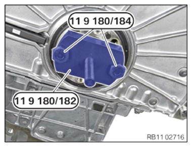
- Secure special tool 0 494 029 (11 9 182)
to the crankshaft using special tool 0 494 031 (11 9 184).
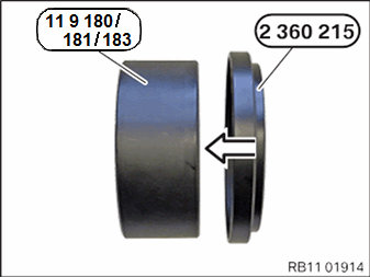
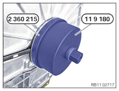
- Connect special tool 2 360215
to special tool 0 494 028 (11 9 181)
in the arrow direction.
- Position special tools 0 494 028 (11 9 181) and 2 360 215 and bring into contact with the crankshaft seal in connection with special tool 0 494 030 (11 9183).
- Check the freedom of movement between the special tool 2 360 215 and the crankshaft sensor during installation.
- Screw in the crankshaft sealing ring up to the stop of the timing case cover using special tool 2 360 215.
Follow-up work
- Refer to REFITTING ENGINE OIL PAN
- Refer to INSTALLING THE FLYWHEEL .
- Refer to INSTALLING STARTER MOTOR
- Refer to INSTALL THE ACOUSTIC COVER FOR THE OIL SUMP .
- Refer to REPLACING THE O-RING ON THE BEARING BRACKET .
- Refer to INSTALL BEARING BRACKET
- Refer to INSTALL FRONT AXLE DIFFERENTIAL
- Refer to SEAL THE OIL DUCT .
- Refer to CLEAN SEALING SURFACES .
- Refer to INSTALLING THE CYLINDER HEAD GASKET .
- Refer to BLOCKING THE CRANKSHAFT IN THE TDC FIRING POSITION OF CYLINDER 1 .
- Refer to INSTALLING THE CYLINDER HEAD .
- Refer to ADJUSTING THE CAMSHAFTS WITH THE SPECIAL TOOL .
- Refer to INSTALLING THE INTAKE ADJUSTER .
- Refer to INSTALLING THE VANOS CENTRAL VALVE OF THE INTAKE ADJUSTER .
- Refer to INSTALL EXHAUST CAMSHAFT ADJUSTER .
- Refer to INSTALLING THE VANOS CENTRAL VALVE OF THE EXHAUST CAMSHAFT ADJUSTER .
- Refer to PRE-TENSIONING THE TIMING CHAIN WITH THE SPECIAL TOOL .
- Refer to TIGHTENING THE VANOS CENTRAL VALVE OF THE EXHAUST CAMSHAFT ADJUSTER .
- Refer to TIGHTENING THE VANOS CENTRAL VALVE OF THE INTAKE ADJUSTER .
- Refer to DISASSEMBLING ALL SPECIAL TOOLS
- Refer to INSTALL CHAIN TENSIONER .
- Refer to CHECKING THE TIMINGS OF THE CAMSHAFT .
- Refer to INSTALLING THE COOLANT LINE BETWEEN THE CYLINDER HEAD AND THE COOLANT PUMP .
- Refer to INSTALLING THE OIL RETURN LINE FOR THE EXHAUST TURBOCHARGER .
- Refer to INSTALLING CYLINDER HEAD COVER .
- Refer to INSTALLING BOTH ACTUATORS .
- Refer to PREPARE THE INJECTORS FOR INSTALLATION .
- Refer to INSTALLING THE HIGH-PRESSURE RAIL WITH INJECTORS OF THE CYLINDERS 4 TO 6 .
- Refer to INSTALLING RAIL WITH INJECTORS OF CYLINDERS 1 TO 3 .
- Refer to INSTALLING THE HIGH-PRESSURE LINE BETWEEN THE HIGH-PRESSURE PUMP AND THE HIGH-PRESSURE RAIL .
- Refer to INSTALLING HIGH PRESSURE PUMP .
- Refer to INSTALLING FUEL DELIVERY LINE .
- Refer to INSTALLING ALL SPARK PLUGS .
- Refer to INSTALL ALL IGNITION COILS .
- Refer to INSTALL CATALYTIC CONVERTER .
- Refer to INSTALLING THE OXYGEN SENSOR MONITOR .
- Refer to INSTALLING LAMBDA OXYGEN SENSOR .
- Refer to INSTALLING THE INTAKE PLENUM .
- Refer to INSTALLING THE TANK VENT VALVE .
- Refer to INSTALLING ACOUSTIC COVER AT REAR .
- Refer to FILLING ENGINE OIL .
- Refer to OPENING THE OIL FILLER CAP .
- Refer to REMOVING THE ENGINE FROM THE ASSEMBLY JIG .
- Refer to MOUNTING THE ENGINE ON THE FRONT AXLE .
- Refer to INSTALLING THE COMPLETE FRONT AXLE INCLUDING ENGINE AND TRANSMISSION .