Removing the cylinder head
WARNING:
Hot surfaces.
Risk of burning!
Risk of burning!
- Perform all work only on components that have cooled down.
WARNING:
Working on fuel system.
Risk of fire! Danger of explosion!
Risk of fire! Danger of explosion!
- When working on the fuel system, make sure the workstation has sufficient ventilation, e.g., by means of extraction.
- Tightly seal off open lines and connections; collect any leakage fuel directly at the point of exit.
- No fire, sparks, open flames or smoking.
CAUTION:
On releasing high pressure line, fuel may emerge at high speed.
Injury hazard!
Injury hazard!
- Wear suitable personal protective equipment.
- Before performing any installation work, allow cooling system to cool down to less than 40°C.
- Note warnings on cylinder head cover.
NOTE:
RISK OF DAMAGE
Engine damage due to missing motor oil.
Missing motor oil following replacement of the cylinder head or the engine can lead to damage on the valve train.
Engine damage due to missing motor oil.
Missing motor oil following replacement of the cylinder head or the engine can lead to damage on the valve train.
- After replacing the cylinder head or the engine, do not start the engine without observing the repair notes.
- It is imperative you observe the repair notes for cylinder head or engine replacement.
- For additional information, see: REPAIR NOTES FOR CYLINDER HEAD OR ENGINE REPLACEMENT
NOTE:
TECHNICAL INFORMATION
Collect and dispose of emerging fluids. Observe country-specific waste disposal regulations.
Collect and dispose of emerging fluids. Observe country-specific waste disposal regulations.
Preliminary work
- Refer to BRING FRONT COMPARTMENT LID IN THE SERVICE POSITION .
- Refer to DEACTIVATING THE 48 V ELECTRICAL SYSTEM .
- Refer to DISCONNECTING ALL BATTERY GROUND LEADS .
- Refer to REMOVING THE ACOUSTIC COVER .
- Refer to REMOVE THE SEAL FOR THE HOOD REAR .
- Refer to REMOVE THE COVER OF THE ENGINE COMPARTMENT AT THE REAR LEFT
- Refer to REMOVE THE COVER OF THE REAR RIGHT ENGINE COMPARTMENT .
- Refer to REMOVE LEFT AND RIGHT WIPER ARM .
- Refer to REMOVE THE COWL COVER .
- Refer to REMOVING TRAILING LINK AT SPRING BOLT .
- Refer to REMOVING THE COWL UPPER PART IN THE CENTER .
- Refer to REMOVING ACOUSTIC COVER AT REAR .
- Refer to REMOVING BOTH ACTUATORS .
- Refer to REMOVING ALL IGNITION COILS
- Refer to REPLACE SPARK PLUGS (540i 2017-2020) , or REMOVING ALL SPARK PLUGS (540i 2021-2022) .
- Refer to REMOVING FUEL DELIVERY LINE .
- Refer to REMOVE THE HIGH PRESSURE LINE BETWEEN THE HIGH PRESSURE PUMP AND THE RAIL .
- Refer to REMOVE HIGH PRESSURE PUMP .
- Refer to REMOVING THE RAIL WITH INJECTORS OF CYLINDERS 1 TO 3 .
- Refer to REMOVING THE RAIL WITH INJECTORS OF CYLINDERS 4 TO 6 .
- Refer to REMOVING THE CYLINDER HEAD COVER .
- Refer to REMOVING THE COVER ON LEFT AND RIGHT IN THE ENGINE COMPARTMENT AT THE TOP .
- Refer to REMOVE BOTH FRONT-END STRUTS .
- Refer to REMOVE FRONT CROSS CONNECTION .
- Refer to REMOVE THE REAR TOP CROSS CONNECTION .
- Refer to REMOVING THE FAN COWL .
- Refer to REMOVING THE INTAKE FILTER HOUSING (TENSION STRUT ON SHOCK TOWER REMOVED) .
- Refer to REMOVING THE RESONATOR WITH THE TOP CLEAN AIR PIPE .
- Refer to REMOVE BOTTOM CLEAN AIR PIPE .
- Refer to REMOVE CHARGE AIR LINE .
- Refer to REMOVE THE HOLDER OF THE POSITIVE BATTERY CABLE .
- Refer to REMOVING THE LAMBDA OXYGEN SENSOR .
- Refer to REMOVING THE OXYGEN SENSOR MONITOR .
- Refer to REMOVING THE DME CONTROL UNIT (540i 2017-2020) , or REMOVING THE DME CONTROL UNIT (540i 2021-2022) .
- Refer to REMOVE THE INTEGRATED POWER SUPPLY MODULE (PDM) (540i 2017-2020) , or REMOVE THE INTEGRATED POWER SUPPLY MODULE (PDM) (540i 2021-2022) .
- Refer to REMOVE CONTROL UNIT BRACKET (540i 2017-2020) , or REMOVING THE CONTROL UNIT HOLDER (540i 2021-2022)
- Refer to REMOVE THE FRONT UNDERBODY PROTECTION OR FRONT THRUST FIELD .
- Refer to REMOVING THE UNDERBODY PROTECTION OF THE STEERING GEAR AND THRUST FIELD RESPECTIVELY .
- Refer to REMOVING THE CENTER UNDERBODY PROTECTION .
- Refer to REMOVING REAR UNDERBODY PROTECTION .
- Refer to REMOVE THE COVER OF THE STEERING ASSEMBLY .
- Refer to REMOVE THE CONNECTING SUPPORT FROM THE TUNNEL .
- Refer to IF INSTALLED: REMOVE THE TORSION STRUT ON THE RIGHT AND LEFT WHERE REQUIRED .
- Refer to REMOVE COMPLETE EXHAUST SYSTEM .
- Refer to REMOVE CATALYTIC CONVERTER .
- Refer to REMOVING THE OIL RETURN LINE FOR THE EXHAUST TURBOCHARGER .
- Refer to DRAIN THE COOLANT FROM THE HIGH-TEMPERATURE COOLING SYSTEM .
- Refer to DRAIN THE COOLANT FROM THE LOW-TEMPERATURE COOLING SYSTEM .
- Refer to CONNECT THE COOLANT LINES FOR THE HIGH-TEMPERATURE COOLANT CIRCUIT .
- Refer to CONNECT THE COOLANT LINES FOR THE LOW-TEMPERATURE COOLANT CIRCUIT .
- Refer to REMOVE TANK VENT VALVE .
- Refer to REMOVING THE INTAKE PLENUM .
- Refer to REMOVE THE COOLANT LINE BETWEEN THE COOLANT PUMP AND CYLINDER HEAD .
- Refer to BLOCKING ENGINE IN TDC FIRING POSITION .
- Refer to REMOVING CHAIN TENSIONER .
- Refer to RELEASING THE VANOS CENTRAL VALVE OF THE INTAKE ADJUSTER .
- Refer to RELEASING VANOS CENTRAL VALVE OF THE EXHAUST CAMSHAFT ADJUSTER .
- Refer to REMOVING THE VANOS CENTRAL VALVE OF THE INTAKE ADJUSTER .
- Refer to REMOVING THE VANOS CENTRAL VALVE OF THE EXHAUST CAMSHAFT ADJUSTER .
- Refer to REMOVING INTAKE ADJUSTER .
- Refer to REMOVE EXHAUST CAMSHAFT ADJUSTER .
- Refer to REMOVE THE TEST GAUGES FOR SECURING THE CAMSHAFTS .
CAUTION:
Heavy component.
Heavy components can lead to injury or damage.
Heavy components can lead to injury or damage.
- Remove and install heavy components with the aid of another person/other persons.
NOTE:
TECHNICAL INFORMATION
Collect and dispose of emerging fluids. Observe country-specific waste disposal regulations.
Collect and dispose of emerging fluids. Observe country-specific waste disposal regulations.
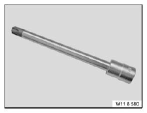
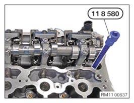
- Prepare special tool 0 495 747 (11 8 580)
.
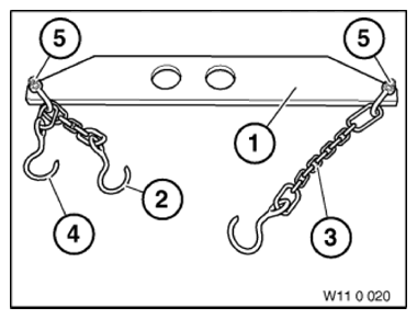
- Prepare special tool 0 490 567 (11 0 020)
.
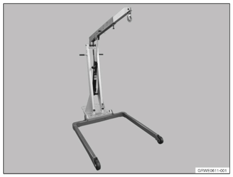
- Prepare the workshop crane 2 220 718
.
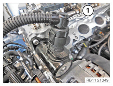
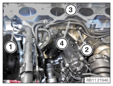
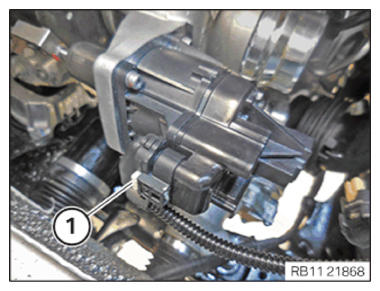
- Unlock plug connection (1) and disconnect.
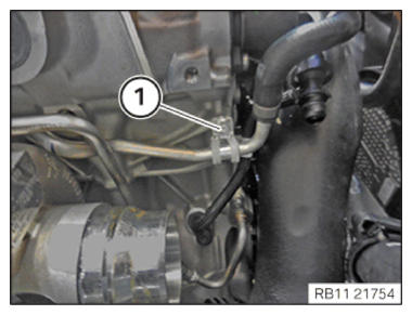
- Unlock and loosen coolant line (1).
- Catch and dispose of leakage coolant.
- Unlock plug connection (2) and disconnect.
- Loosen clamps (3).
- Guide out the wiring harness section (4) for the sensor system 1 and set side.
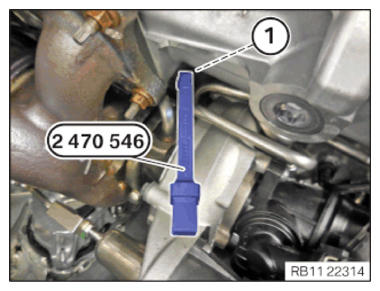
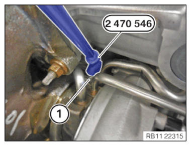
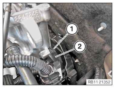
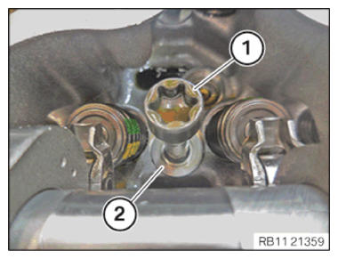
- Loosen screw (1).
- Position special tool 2 470 546
on the screw (1).
- Release the screw (1) using the special tool 2 470 546
.
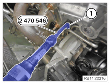
- Feed out the screw (1) using special tool 2 470 546
and remove.
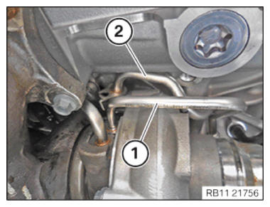
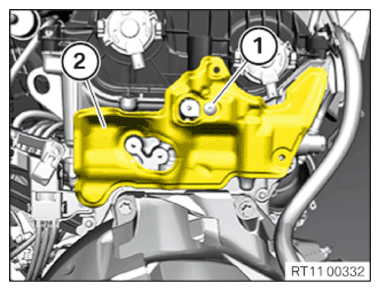
- Feed out the coolant return line (2) for the exhaust turbocharger and set it aside.
- Feed out the oil feed line (1) for the exhaust turbocharger and set it aside.
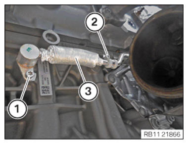
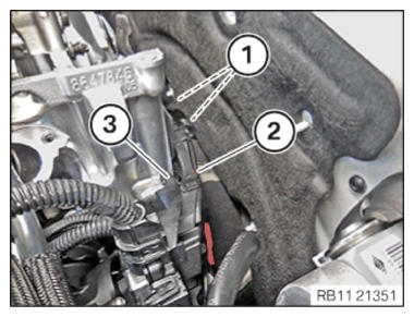
- Loosen screws (1) and (2).
- Feed the coolant feed line for the exhaust turbocharger (3) out of the crankcase and place aside.
- Catch and dispose of leakage coolant.
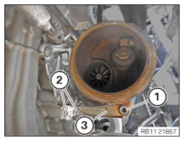
- Loosen screws (1) and (2).
- Feed out the support (3) and remove it.
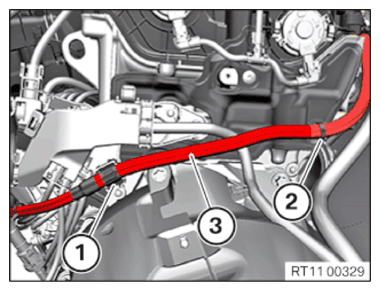
- Unlock plug connection (1) and disconnect.
- Unlock and release the clamps (1) and (2).
- Thread out positive battery cable (3) and set it aside.
- Loosen screws (1).
- Feed out the transmission wiring harness (2) on the wiring harness section (3) for sensor system 1 and place to one side.
- Loosen screw (1).
- Feed out the wiring harness section (2) for sensor system 1 and place to one side.
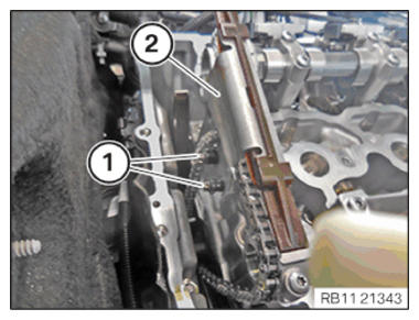
NOTE:
The figure shows the rear of the engine.
- Loosen screw (1).
- Guide out and remove the cover (2).
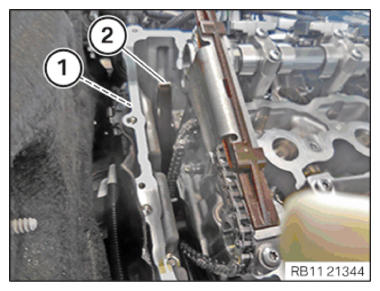
- Loosen screws (1).
- Guide out and remove slide rail (2).
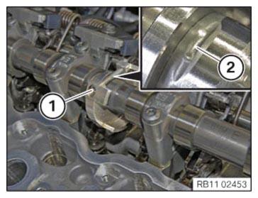
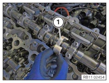
- Unscrew the bearing journal (1) from the guide rail (2).
- Rotate intake camshaft, if necessary in the position shown.
The recess (2) must point up.
- Loosen screw (1).
- Shift the camshaft sensor wheel (1) in direction of cylinder 1 and feed out from the intake camshaft.
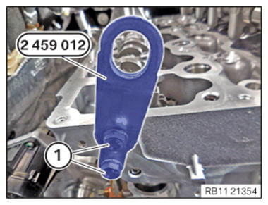
- Insert and position the special tool 2 459 012 at the cylinder head.
- Tighten the screws (1) of the special tool 2 459 012 .
TIGHTENING TORQUES SPECIFICATION
| Special tool to cylinder head | ||
| M8 | Tightening torque | 21.5 Nm |
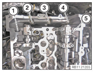
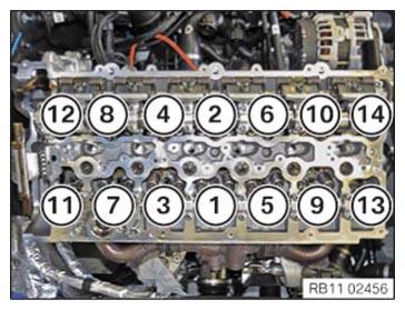
- Loosen the cylinder head bolts in the sequence from (5) to (1).
- Loosen the cylinder head bolts with the special tool 0 495 747 (11 8 580)
.
- Undo the screws using the special tool 0 495 747 (11 8 580) in the order (14) to (1).
- Feed out and remove all the cylinder head bolts (1).
- Feed out and remove all the washers (2).
CAUTION:
Heavy component.
Heavy components can lead to injury or damage.
Heavy components can lead to injury or damage.
- Remove and install heavy components with the aid of another person/other persons.
NOTE:
RISK OF DAMAGE
Damage to guide rails.
The application of great force can damage the guide rails of the timing chain.
Damage to guide rails.
The application of great force can damage the guide rails of the timing chain.
- When removing and installing the cylinder head, make sure that the cylinder head does not damage the guide rail.
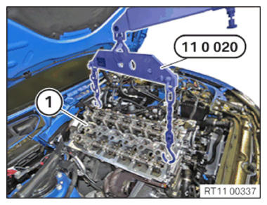
- Attach special tool 0 490 567 (11 0 020) to workshop crane.
- Lift out the cylinder head (1) and the exhaust turbocharger with the help of a second person, using the workshop crane and the special tool 0 490 567 (11 0 020) .