Remove intake camshaft
NOTE:
DANGER
High-voltage system.
The high-voltage system operates on the basis of hazardous, electrical voltage and high currents. Danger to life through electric shock!
High-voltage system.
The high-voltage system operates on the basis of hazardous, electrical voltage and high currents. Danger to life through electric shock!
- All work on the high-voltage system may only be carried out by specially trainee and technically experienced personnel.
- For additional information see:
- For additional information see:
WARNING:
Working on 12 V vehicle electrical system.
Risk of short circuits! Risk of fire!
Risk of short circuits! Risk of fire!
- Make sure that no charger is connected to the jump start support point in the engine compartment.
- Detach battery earth lead from battery.
- With auxiliary batteries: Detach all battery earth leads from additional batteries.
WARNING:
Working on fuel system.
Risk of fire! Danger of explosion!
Risk of fire! Danger of explosion!
- When working on the fuel system, make sure that the workbay is sufficiently ventilated, e.g. using extraction unit.
- Tightly seal off open lines and connections; collect any escaping fuel directly at the point of exit.
- No fire, sparks, open flames or smoking.
CAUTION:
On releasing high pressure line, fuel may emerge at high speed.
Danger of injury!
Danger of injury!
- Wear suitable personal protective equipment.
- Allow the cooling system to cool down to a temperature below 40°C before starting installation work.
- Note warnings on cylinder head cover.
NOTE:
RISK OF DAMAGE
Damage to battery terminal, the safety battery terminal or the intelligent battery sensor (IBS).
Damaged battery terminals can lead to malfunctions or vehicle electrical system faults.
Damage to battery terminal, the safety battery terminal or the intelligent battery sensor (IBS).
Damaged battery terminals can lead to malfunctions or vehicle electrical system faults.
- Pull off battery terminal from battery pole by carefully moving to and fro. Do not pry off using a tool.
NOTE:
TECHNICAL INFORMATION
Collect and dispose of emerging fluids. Observe country-specific waste disposal regulations.
Collect and dispose of emerging fluids. Observe country-specific waste disposal regulations.
NOTE:
TECHNICAL INFORMATION
After replacing one or more VANOS central valves or VANOS adjuster:
During removal, note the identification/part number of the VANOS central valve or VANOS adjuster and write it down.
A VANOS adjuster and/or central valve with the same part number must always be reinstalled. Mixed installation is not permitted.
Read out I level of the vehicle and the proceed accordingly.
It is imperative to observe Product and Measures Management Aftersales measure 64122020.
For further information, see the applicable BMW parts catalogue
Preliminary works
- Refer to BRINGING FRONT COMPARTMENT LID IN THE SERVICE POSITION .
- Refer to REMOVING THE ACOUSTIC COVER .
- Refer to REMOVING THE COVER OF THE ENGINE COMPARTMENT AT THE REAR LEFT .
- Refer to REMOVING THE SEAL FOR THE REAR BONNET .
- Refer to REMOVING LEFT AND RIGHT WIPER ARM .
- Refer to REMOVING COWL PANEL COVER .
- Refer to REMOVING TRAILING LINK AT SPRING BOLT .
- Refer to REMOVING THE CENTER BULKHEAD UPPER PART .
- Refer to REMOVING THE RIGHT SEALING FRAME .
- Refer to LOOSENING HIGH-VOLTAGE CABLES ON THE ELECTRICAL MACHINE ELECTRONICS .
- Refer to REMOVING ACOUSTIC COVER AT REAR .
- Refer to REMOVING LEFT SEALING FRAME .
- Refer to REMOVING THE CENTER BULKHEAD LOWER SECTION .
- Refer to REMOVING INTAKE SILENCER HOUSING .
- Refer to REMOVING RESONATOR .
- Refer to REMOVING CLEAN AIR PIPE .
- Refer to REMOVING CHARGE AIR LINE .
- Refer to REMOVING THE CYLINDER HEAD COVER ACOUSTIC COVER .
- Refer to REMOVING IGNITION COILS .
- Refer to REMOVING ALL SPARK PLUGS .
- Refer to REMOVING THE HIGH PRESSURE LINE BETWEEN THE HIGH PRESSURE PUMP AND THE RAIL .
- Refer to REMOVING FUEL DELIVERY LINE .
- Refer to REMOVING HIGH PRESSURE PUMP .
- Refer to REMOVING INJECTORS .
- Refer to REMOVING THE DME CONTROL UNIT .
- Refer to REMOVING THE INTEGRATED POWER SUPPLY MODULE (PDM) .
- Refer to REMOVING CONTROL UNIT HOLDER .
- Refer to REMOVING THE FRONT UNDERBODY PROTECTION OR FRONT THRUST FIELD .
- Refer to REMOVING THE UNDERBODY PROTECTION OF THE STEERING GEAR AND FRONT STIFFENING PLATE RESPECTIVELY .
- Refer to REMOVING REAR STIFFENING PLATE .
- Refer to DRAINING THE COOLANT FROM THE HIGH-TEMPERATURE COOLING SYSTEM .
- Refer to DRAINING THE COOLANT FROM THE LOW-TEMPERATURE COOLING SYSTEM .
- Refer to PARTIALLY RELEASING ACOUSTIC COVER OF OIL SUMP .
- Refer to REMOVING THE THERMOSTAT FROM THE TRANSMISSION OIL LINES .
- Refer to REMOVING THE ACOUSTIC COVER FOR THE ENGINE AT THE FRONT .
- Refer to REMOVING AUXILIARY COOLANT PUMP FOR THE EXHAUST TURBOCHARGER .
- Refer to REMOVING FRONT ENGINE ENCAPSULATION .
- Refer to REMOVING BOTH ACTUATORS .
- Refer to REMOVING THE CYLINDER HEAD COVER .
- Refer to REMOVING TANK VENTING VALVE .
- Refer to REMOVING INTAKE PLENUM .
- Refer to REMOVING THE SERVOMOTOR FOR THE ECCENTRIC SHAFT .
- Refer to CHECKING THE POSITION OF THE INTAKE CAMSHAFT .
- Refer to REMOVING TORSION SPRINGS .
- Refer to REMOVING ALL GATES .
- Refer to REMOVING ALL INTERMEDIATE LEVERS .
- Refer to TURNING THE ENGINE ON THE VIBRATION DAMPER .
- Refer to BLOCKING THE CAMSHAFTS .
- Refer to BLOCKING THE CRANKSHAFT IN THE TDC FIRING POSITION OF CYLINDER 1 .
- Refer to REMOVING CHAIN TENSIONER .
- Refer to RELEASING THE VANOS CENTRAL VALVE .
- Refer to REMOVING VANOS CENTRAL VALVE OF THE INTAKE SIDE .
- Refer to REMOVING INTAKE ADJUSTER .
- Refer to DISASSEMBLING THE SPECIAL TOOL 2 358 122 .
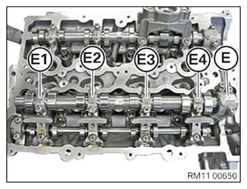
- Make sure that the exhaust camshaft bearing cap is placed in the correct position in the special tool 0 495 105 (11 4 480). NOTE: The intake sprocket bearing caps are legibly labeled from the intake side with E1, E2, E3, E4 and E.NOTE: Intake camshaft bearing cap E is a thrust bearing.
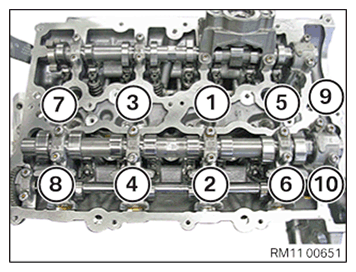
- Loosen all screws on the intake camshaft bearing caps in sequence from (10) to (1).
- Take off intake camshaft bearing caps (E1), (E2), (E3), (E4) and (E) and place them in order in the special tool 0 495 105 (11 4 480).
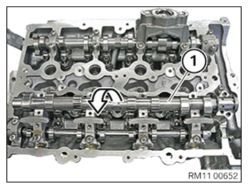
- Remove the intake shaft (1) in the direction of the arrow.