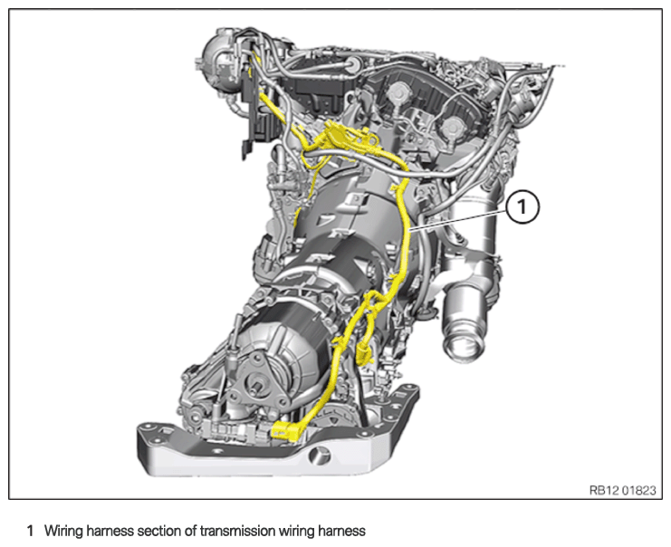
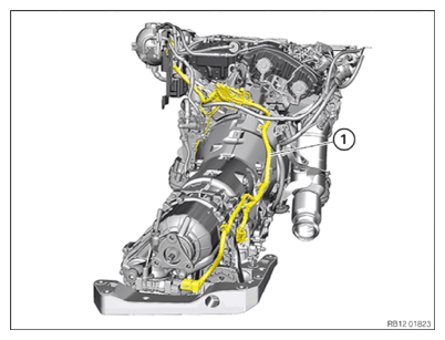
Install the wiring harness section of the transmission wiring harness
Wiring harness section of transmission wiring harness
NOTE:
RISK OF DAMAGE
Improper routing of cables and wiring harnesses.
Trapped, crushed or damaged cables may cause short circuits and malfunctions.
Improper routing of cables and wiring harnesses.
Trapped, crushed or damaged cables may cause short circuits and malfunctions.
- Route all cables without abrasions, do not trap and crush.
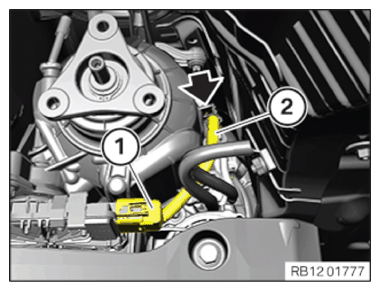
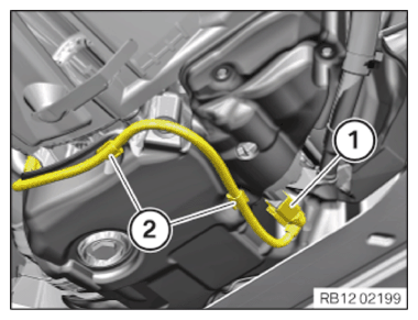
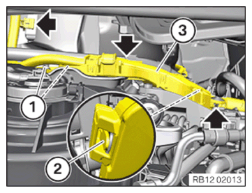
- Insert and install the wiring harness (1) for the transmission module.
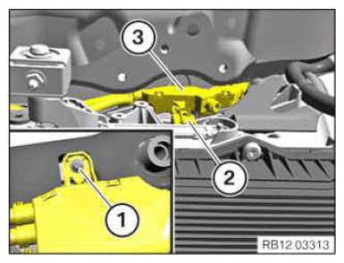
- Guide in and install wiring harness section (3) of the transmission wiring harness.
- Connect connectors (2) and lock.
The connector (2) must engage audibly.
- Tighten down screw (1).TIGHTENING TORQUES SPECIFICATION
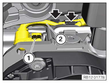
Grounding cable/wiring harness section to transmission BM6 Tightening torque 8 Nm - Feed in and install the wiring harness section (2) of the transmission wiring harness.
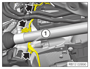
- Secure the clamps (arrows).
- Connect connectors (1) and lock.
The connector (1) must engage audibly.
- Thread in the wiring harness section (2) of the supply module and install.
- Secure clamp (arrow).
- Connect connectors (1) and lock.
The connector (1) must engage audibly.
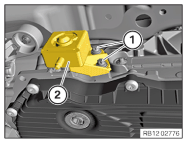
- Insert and install the holder (2).
- Replace screws (1).
- Tighten the screws (1).
TIGHTENING TORQUES SPECIFICATION
| Holder on the transmission | ||
| Torx screw BM8 Replace screws. | Tightening torque | 19 Nm |
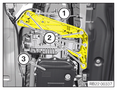
Fastening the transmission
- Move the transmission (3) to the installation position.
- Replace screws (2).
Parts: Screws
- Tighten down screws (2).
TIGHTENING TORQUES SPECIFICATION
| Transmission cross member to body | ||
| M8 | Tightening torque | 19 Nm |
- Secure the cable with the clamp (1).
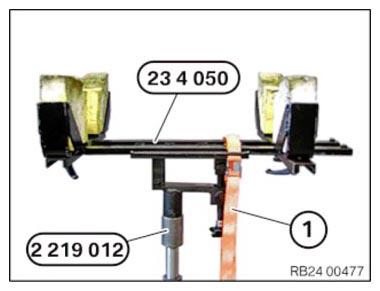
- Loosening the luggage strap (1).
- Remove special tools 2 219 012
and 0 495 498 (23 4 050).
- Secure clamps (2).
- Connect connectors (1) and lock.
The connector (1) must engage audibly.
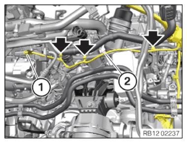
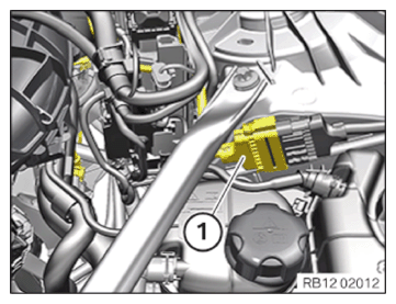
- Feed in and install the wiring harness section (1) of the transmission wiring harness.
- Secure the clamps (arrows).
- Feed in and install the wiring harness section (2) of the transmission wiring harness.
- Secure clamp (arrow).
- Connect connectors (1) and lock.
The connector (1) must engage audibly.
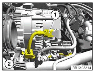
- Secure the clamp (2).
- Connect connectors (1) and lock.
The connector (1) must engage audibly.
- Feed in and install the wiring harness section (3) of the transmission wiring harness.
- Make sure the locking mechanism (2) engages audibly.
- Tighten down screws (1).TIGHTENING TORQUES SPECIFICATION
Cable bracket on rear cylinder head/transmission M6 x 20 Tightening torque 8 Nm - Secure the clamps (arrows).
- Connect connectors (1) and lock.
The connector (1) must engage audibly.
Follow-up work
- Refer to INSTALLING THE INTAKE PLENUM .
- Refer to INSTALLING THE TANK VENT VALVE .
- Refer to INSTALLING THE CONTROL UNIT HOLDER .
- Refer to PARTIALLY INSTALLING THE INTEGRATED POWER SUPPLY MODULE (PDM) .
- Refer to INSTALLING THE DME CONTROL UNIT .
- Refer to INSTALLING FAN COWL .
- Refer to INSTALLING THE REAR TOP CROSS CONNECTION .
- Refer to INSTALLING FRONT CROSS CONNECTION .
- Refer to INSTALLING BOTH FRONT-END STRUTS .
- Refer to INSTALLING THE COVER ON THE LEFT AND RIGHT IN THE ENGINE COMPARTMENT AT THE TOP .
- Refer to FASTENING THE PROP SHAFT (PARTIALLY REMOVED) .
- Refer to INSTALLING THE HEAT SHIELDS .
- Refer to INSTALLING TRANSMISSION MOUNTING BRACKET (ALL-WHEEL DRIVE VEHICLE) .
- Refer to INSTALLING THE TRANSMISSION BEARING SUPPORT (ALL-WHEEL DRIVE VEHICLE) .
- Refer to INSTALLING THE COMPLETE EXHAUST SYSTEM .
- Refer to IF INSTALLED: INSTALL THE TORSION STRUT ON THE RIGHT, AND ON THE LEFT WHERE REQUIRED .
- Refer to INSTALLING THE CONNECTING SUPPORTS ON THE TUNNEL .
- Refer to CONNECTING NEGATIVE BATTERY CABLE .
- Refer to ACTIVATING THE 48 V ELECTRICAL SYSTEM .
- Refer to FILLING AND VENTING THE LOW-TEMPERATURE COOLANT CIRCUIT .
- Refer to INSTALLING THE UNDERBODY PROTECTION OF THE STEERING GEAR OR THE FRONT THRUST FIELD .
- Refer to INSTALLING THE FRONT UNDERBODY PROTECTION OR FRONT THRUST FIELD .
- Refer to INSTALLING THE THRUST FIELD .
- Refer to INSTALLING REAR UNDERBODY PROTECTION .
- Refer to INSTALLING ACOUSTIC COVER AT REAR .
- Refer to INSTALLING ACOUSTIC COVER .
- Refer to INSTALLING THE CENTER COWL UPPER PART .
- Refer to INSTALLING TENSION STRUT ON SHOCK TOWER .
- Refer to INSTALLING WINDSHIELD PANEL COVER .
- Refer to INSTALLING LEFT AND RIGHT WIPER ARM .
- Refer to INSTALLING THE REAR RIGHT ENGINE COMPARTMENT COVER .
- Refer to INSTALLING THE COVER OF THE ENGINE COMPARTMENT ON THE REAR LEFT .
- Refer to INSTALLING THE FRONT HOOD SEAL AT THE REAR .
- Refer to TAKING HOOD OUT OF THE SERVICE POSITION .