Installing both exhaust manifolds
NOTE:
Perform the steps on the right and left side.
NOTE:
To provide a better overview: Illustration of surrounding parts removed.
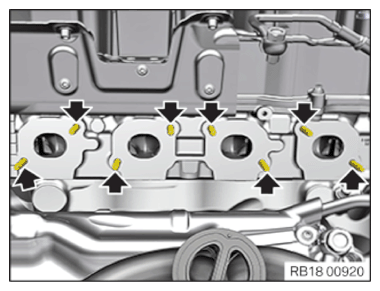
- Replace stud bolts (arrows).
Parts: Stud bolts
- Tighten stud bolts (arrows).TIGHTENING TORQUES SPECIFICATION
Stud bolt on cylinder head M8x50
Replace the stud boltTightening torque 20 Nm NOTE: RISK OF DAMAGE
Damage to the surface.
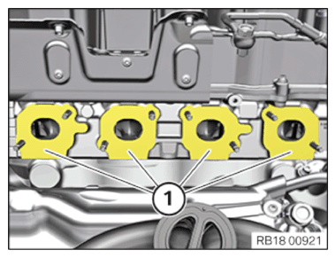
The use of metal-cutting tools (e.g., emery cloths) for cleaning surfaces can damage them and lead to leaks and/or engine damage.- Do not use any metal-cutting tools.
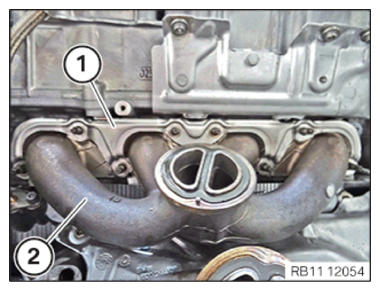
NOTE: To provide a better overview: Illustration of surrounding parts removed. - Clean the sealing surfaces (1) on the cylinder head using special tool 0 495 102 (11 4 470).
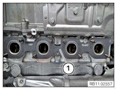
- Replace the seal (1).
Parts: Gasket
- The installation position of the seal
(1) must be adhered to.
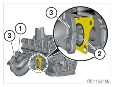
The seal (1) must be installed with the side of the bead (2) (seal cavity) toward the exhaust manifold (3).
- Insert and install the exhaust manifold (2).
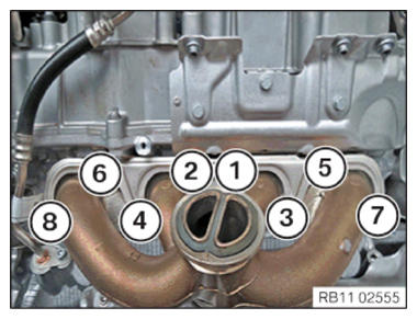
- Position the sliding rail (1).NOTE: TECHNICAL INFORMATION
When assembling, it is essential to observe screwing sequences and tightening torques.
Failure to comply with the regulations can lead to leaks and damage. - Replace nuts (1) to (8).
Parts: Nuts
- Tighten the nuts in sequence (1) to (8).TIGHTENING TORQUES SPECIFICATION
Exhaust manifold to cylinder head M8 Replace nuts. Tightening torque 15 Nm
Follow-up work
- Refer to INSTALLING FRONT HEAT SHIELD .
- Refer to INSTALL ALTERNATOR .
- Refer to INSTALLING BOTH EXHAUST TURBOCHARGERS .
- Refer to ATTACHING THE CHARGE AIR COOLER .
- Refer to INSTALLING THE CLEAN AIR PIPE OF CYLINDER BANK 2 .
- Refer to CONNECTING THE LEFT CHARGE AIR LINE TO THE EXHAUST TURBOCHARGER .
- Refer to INSTALLING CLEAN AIR PIPE OF CYLINDER BANK 1 .
- Refer to CONNECTING THE RIGHT CHARGE AIR LINE TO THE EXHAUST TURBOCHARGER .
- Refer to CLOSING THE HIGH-TEMPERATURE COOLANT CIRCUIT .
- Refer to INSTALLING THE UNDERBODY PROTECTION OF THE STEERING GEAR OR THE FRONT THRUST FIELD .
- Refer to INSTALL THE FRONT UNDERBODY PROTECTION OR FRONT THRUST FIELD .
- Refer to INSTALLING THE FRONT LEFT BOTTOM WHEEL ARCH COVER .
- Refer to INSTALLING THE FRONT BOTTOM RIGHT WHEEL ARCH COVER .
- Refer to INSTALL DRIVE BELT .
- Refer to PARTLY FASTENING THE COOLANT EXPANSION TANK FOR THE LOW-TEMPERATURE COOLANT CIRCUIT .
- Refer to INSTALLING FAN COWL .
- Refer to INSTALL THE REAR TOP CROSS CONNECTION .
- Refer to INSTALL FRONT CROSS CONNECTION .
- Refer to INSTALLING THE RIGHT INTAKE FILTER HOUSING WITH THE RIGHT FRONT-END STRUT .
- Refer to INSTALLING LEFT INTAKE FILTER HOUSING WITH LEFT FRONT-END STRUT .
- Refer to INSTALLING THE COVER ON THE LEFT AND RIGHT IN THE ENGINE COMPARTMENT AT THE TOP
- Refer to INSTALLING THE LEFT AND RIGHT CATALYTIC CONVERTERS
- Refer to RELEASING THE HEAT SHIELD .
- Refer to INSTALLING THE CENTER COWL UPPER PART .
- Refer to INSTALL TENSION STRUT ON SHOCK TOWER .
- Refer to INSTALLING WINDSHIELD PANEL COVER .
- Refer to INSTALL LEFT AND RIGHT WIPER ARM .
- Refer to INSTALL THE REAR RIGHT ENGINE COMPARTMENT COVER .
- Refer to INSTALL THE COVER OF THE ENGINE COMPARTMENT ON THE REAR LEFT .
- Refer to INSTALLING THE LEFT AND RIGHT HEAT SHIELD
- Refer to INSTALL HEAT SHIELD, TOP .
- Refer to INSTALLING THE RIGHT OXYGEN SENSOR MONITOR .
- Refer to INSTALLING THE LEFT OXYGEN SENSOR MONITOR .
- Refer to PARTLY INSTALLING THE RIGHT LAMBDA OXYGEN SENSOR .
- Refer to PARTIALLY INSTALLING THE LEFT LAMBDA OXYGEN SENSOR .
- Refer to INSTALLING THE RETAINING BRIDGE IN VEHICLES WITH A GASOLINE PARTICULATE FILTER .
- Refer to INSTALL EXHAUST SYSTEM .
- Refer to INSTALLING CENTER REAR UNDERSHIELD .
- Refer to INSTALL THE CONNECTING SUPPORTS ON THE TUNNEL .
- Refer to DISCONNECTING ALL BATTERY GROUND LEADS .
- Refer to FILL AND VENT THE HIGH-TEMPERATURE COOLANT CIRCUIT .
- Refer to CHECK ENGINE OIL LEVEL .