Installing the rear timing case cover
Further information is available.
NOTE:
TECHNICAL INFORMATION
The sealing surfaces must be free of oil, grease and cleaning agents.
The sealing surfaces must be free of oil, grease and cleaning agents.
NOTE:
RISK OF DAMAGE
Damage to the surface.
The use of metal-cutting tools (e.g., emery cloths) for cleaning surfaces can damage them and lead to leaks and/or engine damage.
Damage to the surface.
The use of metal-cutting tools (e.g., emery cloths) for cleaning surfaces can damage them and lead to leaks and/or engine damage.
- Do not use any metal-cutting tools.
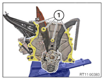
- Clean sealing surfaces (1) with special tool 0 495 102 (11 4 470) .
- Clean the sealing surface (1) with the brake cleaner.
CONSUMABLE - BRAKE CLEANER DESCRIPTION
| Brake cleaner 2.0 | 500 ml, Spray can | 83192365214 |
| 20, Canister | 83192365215 |
NOTE:
RISK OF DAMAGE
Damage to the surface.
The use of metal-cutting tools (e.g., emery cloths) for cleaning surfaces can damage them and lead to leaks and/or engine damage.
Damage to the surface.
The use of metal-cutting tools (e.g., emery cloths) for cleaning surfaces can damage them and lead to leaks and/or engine damage.
- Do not use any metal-cutting tools.
NOTE:
TECHNICAL INFORMATION
The sealing surfaces must be free of oil, grease and cleaning agents.
The sealing surfaces must be free of oil, grease and cleaning agents.
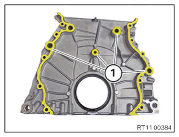
- Clean sealing surfaces (1) with special tool 0 495 102 (11 4 470) .
- Clean the sealing surface (1) with the brake cleaner.
CONSUMABLE - BRAKE CLEANER DESCRIPTION
| Brake cleaner 2.0 | 500 ml, Spray can | 83192365214 |
| 20, Canister | 83192365215 |
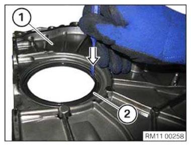
- Position the timing case cover (1) underneath.
- Position punch on inner side of crankshaft seal (2).
- Remove crankshaft sealing ring (2) in direction of arrow outward.
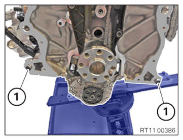
- Check the fitting sleeves (1) for damage, replace if necessary.
- Check for correct fit of fitting sleeves (1).
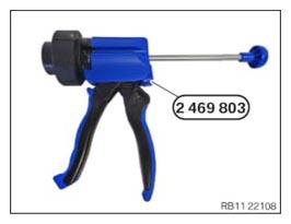
- Have the special tool 2 469 803 ready.
NOTE:
TECHNICAL INFORMATION
For additional information see: OVERVIEW OF CONSUMABLES (BMW PARTS CATALOGUE)
For additional information see: OVERVIEW OF CONSUMABLES (BMW PARTS CATALOGUE)
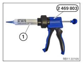
- Position the sealing compound (1) as shown on the special tool 2 469 803
.
Parts : Sealing compound
NOTE:
TECHNICAL INFORMATION
The processing time of the liquid sealing compound can be at a maximum of 10 min.
Commissioning of the assembly is not possible until 25 minutes after the processing time.
The processing time of the liquid sealing compound can be at a maximum of 10 min.
Commissioning of the assembly is not possible until 25 minutes after the processing time.
Non-observance can lead to leaks in the assembly.
- Apply the sealing compound in area (1) along the inner edge.
Sealing compound
| Loctite 5970 liquid sealing compound Processing time <10 minutes at room temperature |
50 ml, Cartridge | 83190404517 |
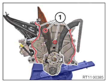
TECHNICAL DATA - HEIGHT OF SEALING BEAD SPECIFICATION
| Height of the sealing bead | |
| 2.0 mm... 2.5 mm | |
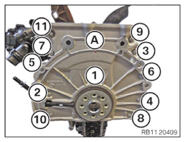
- Replace screws (1) to (11).
Parts : Screws
- Carefully mount the timing case cover (A).
- Tighten the screws in sequence (1) to (11) with the special tool 0 490 504 (00 9 120) .
TIGHTENING TORQUES SPECIFICATION
| Rear timing case cover on crankcase | ||
| M6 x 31 Replace screws. |
Joining torque Angle of rotation |
8 Nm 90° |
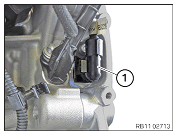
- Connect connectors (1) and lock.
The connector (1) must engage audibly.
Installing the rear crankshaft seal
NOTE:
TECHNICAL INFORMATION
The radial shaft seal must be installed dry. Do not use motor oil or lubricant.
The radial shaft seal must be installed dry. Do not use motor oil or lubricant.
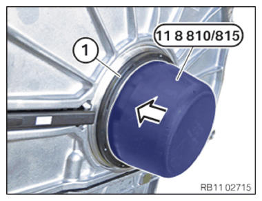
- Install special tool 0 496 137 (11 8 815) on the crankshaft.
- Pull off crankshaft sealing ring (1) in the arrow direction using special tool 0 496 137 (11 8 815)
so that crankshaft sealing ring (1) rests all around the timing case cover.
- Guide the special tool 0 496 137 (11 8 815) out and remove.
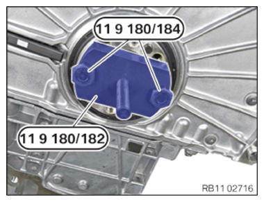
- Secure special tool 0 494 029 (11 9 182)
to the crankshaft using special tool 0 494 031 (11 9 184)
.
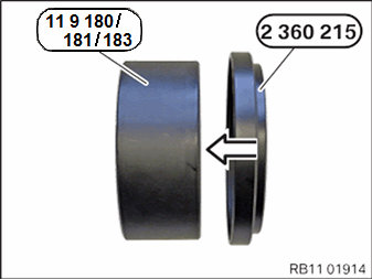
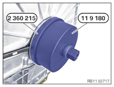
- Connect special tool 2 360 215
to special tool 0 494 028 (11 9 181)
in the arrow direction.
- Position special tools 0 494 028 (11 9 181) and 2 360 215 and bring into contact with the crankshaft seal in connection with special tool 0 494 030 (11 9 183) .
- Check the freedom of movement between the special tool 2 360 215 and the crankshaft sensor during installation.
- Screw in the crankshaft sealing ring up to the stop of the timing case cover using special tool 2 360 215 .
Follow-up work
- Refer to REFITTING ENGINE OIL PAN .
- Refer to INSTALLING THE FLYWHEEL .
- Refer to INSTALLING STARTER MOTOR
- Refer to INSTALL THE ACOUSTIC COVER FOR THE OIL SUMP .
- Refer to SEAL THE OIL DUCT .
- Refer to CLEAN SEALING SURFACES .
- Refer to INSTALLING THE CYLINDER HEAD GASKET .
- Refer to BLOCKING THE CRANKSHAFT IN THE TDC FIRING POSITION OF CYLINDER 1 .
- Refer to INSTALLING THE CYLINDER HEAD .
- Refer to ADJUSTING THE CAMSHAFTS WITH THE SPECIAL TOOL .
- Refer to INSTALLING THE INTAKE ADJUSTER .
- Refer to INSTALLING THE VANOS CENTRAL VALVE OF THE INTAKE ADJUSTER .
- Refer to INSTALL EXHAUST CAMSHAFT ADJUSTER .
- Refer to INSTALLING THE VANOS CENTRAL VALVE OF THE EXHAUST CAMSHAFT ADJUSTER .
- Refer to PRE-TENSIONING THE TIMING CHAIN WITH THE SPECIAL TOOL .
- Refer to TIGHTENING THE VANOS CENTRAL VALVE OF THE EXHAUST CAMSHAFT ADJUSTER .
- Refer to TIGHTENING THE VANOS CENTRAL VALVE OF THE INTAKE ADJUSTER .
- Refer to DISASSEMBLING ALL SPECIAL TOOLS
- Refer to INSTALL CHAIN TENSIONER .
- Refer to CHECKING THE TIMINGS OF THE CAMSHAFT .
- Refer to INSTALLING THE COOLANT LINE BETWEEN THE CYLINDER HEAD AND THE COOLANT PUMP .
- Refer to INSTALLING THE OIL RETURN LINE FOR THE EXHAUST TURBOCHARGER .
- Refer to INSTALLING CYLINDER HEAD COVER .
- Refer to INSTALLING BOTH ACTUATORS .
- Refer to PREPARE THE INJECTORS FOR INSTALLATION .
- Refer to INSTALLING THE HIGH-PRESSURE RAIL WITH INJECTORS OF THE CYLINDERS 4 TO 6 .
- Refer to INSTALLING RAIL WITH INJECTORS OF CYLINDERS 1 TO 3 .
- Refer to INSTALLING THE HIGH-PRESSURE LINE BETWEEN THE HIGH-PRESSURE PUMP AND THE HIGH-PRESSURE RAIL .
- Refer to INSTALLING HIGH PRESSURE PUMP .
- Refer to INSTALLING FUEL DELIVERY LINE .
- Refer to REPLACE SPARK PLUGS (540i 2017-2020) , or INSTALLING ALL SPARK PLUGS (540i 2021-2022) .
- Refer to INSTALL ALL IGNITION COILS .
- Refer to INSTALL CATALYTIC CONVERTER .
- Refer to INSTALLING THE OXYGEN SENSOR MONITOR .
- Refer to INSTALLING LAMBDA OXYGEN SENSOR .
- Refer to INSTALLING THE INTAKE PLENUM .
- Refer to INSTALLING THE TANK VENT VALVE .
- Refer to INSTALLING ACOUSTIC COVER AT REAR .
- Refer to POUR IN MOTOR OIL (MOTOR OIL CHANGE) (540i 2017-2020) , or FILLING ENGINE OIL (540i 2021-2022) .
- Refer to RELEASING THE OIL FILTER COVER (540i 2017-2020) , or REMOVING THE OIL FILLER CAP (540i 2017-2020) .
- Refer to REMOVING THE ENGINE FROM THE ASSEMBLY JIG .
- Refer to MOUNTING THE ENGINE ON THE FRONT AXLE .
- Refer to INSTALLING THE COMPLETE FRONT AXLE INCLUDING ENGINE AND TRANSMISSION .