Install exhaust camshaft
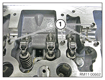
- Check the fitting sleeves (1) for a correct
fit and damage, replace if necessary.
- Coat all bearing positions (1) with fresh
engine oil.
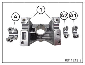
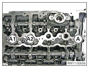
- Clean all bearing positions of the exhaust camshaft bearing cap (A1), (A2) and (A) and coat with fresh engine oil.
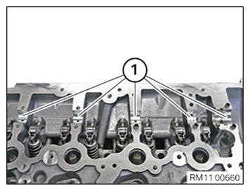
- Clean the bearing positions (1) of the high pressure pump bracket and coat with fresh
engine oil.
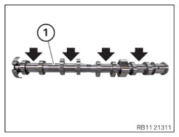
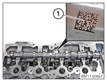
- Clean all the bearing positions (arrows) of the exhaust camshaft (1) and coat with fresh
engine oil.
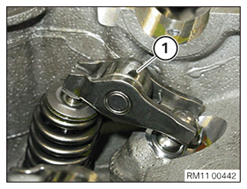
- Make sure that the roller cam follower (1) is fitted correctly before installing the exhaust camshaft.
- Coat the exhaust camshaft and the exhaust camshaft bearing cap with fresh engine oil.
- Insert exhaust camshaft in the cylinder head, such that the mark (1) points upwards. NOTE: TECHNICAL INFORMATION
The camshaft bearing caps must not be mixed up. The camshaft bearing caps must be installed in the installation position from which they were removed. - Position the exhaust camshaft bearing cap (A1), (A2) and (A) on the cylinder head.NOTE: The exhaust camshaft bearing caps are legibly labelled from the intake side and marked with A1, A2 and A.NOTE: Exhaust camshaft bearing cap A is a thrust bearing.
- Check the tensile strength of the screws for the bearing caps.
The figure shows screws with the tensile strength 8.8.
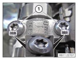
- Check the tensile strength of the screws for the bearing caps.
The figure shows screws with the tensile strength 10.9.
NOTE: TECHNICAL INFORMATION
The camshaft is tensioned by the valve springs. Tighten or loosen each screw on the camshaft bearing caps one at a time in the specified sequence and by half a turn only. Repeat procedure. - Coat both bearing positions on the high pressure pump bracket with fresh engine oil.
- Position the high pressure pump bracket on the cylinder head.
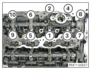
- Join all bolts of the exhaust camshaft bearing caps in sequence (1) to (10) in half turns.
- Adhere to the jointing torque.
- Tighten all bolts of the exhaust camshaft bearing caps in sequence (1) to (10).TIGHTENING TORQUES SPECIFICATION
Exhaust camshaft to cylinder head M6
Tensile strength of screw 8.8Tightening torque 9.6 Nm Tightening torque 9.6 Nm M6
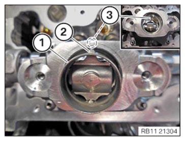
Tensile strength of screw 10.9Tightening torque 11.8 Nm Tightening torque 11.8 Nm - Guide in and position roller tappet (1).
- Ensure that pin (2) is positioned correctly in guide (3).
- Feed in and install roller tappet (1).

Follow-up Work
- Refer to INSTALLING EXHAUST CAMSHAFT ADJUSTER .
- Refer to BLOCKING THE CAMSHAFTS .
- Refer to PRELOAD TIMING CHAIN .
- Refer to TIGHTENING THE VANOS CENTRAL VALVE .
- Refer to DISASSEMBLING ALL SPECIAL TOOLS .
- Refer to CHECKING CAMSHAFT TIMING .
- Refer to INSTALLING THE THERMOSTAT ON THE TRANSMISSION OIL LINES .
- Refer to SECURING THE OIL SUMP ACOUSTIC COVER .
- Refer to INSTALLING CYLINDER HEAD COVER .
- Refer to INSTALLING BOTH ACTUATORS .
- Refer to PREPARING THE INJECTORS FOR INSTALLATION .
- Refer to INSTALLING INJECTORS .
- Refer to PREPARING FOR THE INSTALLATION OF THE HIGH PRESSURE PUMP .
- Refer to INSTALLING HIGH PRESSURE PUMP .
- Refer to INSTALLING FUEL DELIVERY LINE .
- Refer to INSTALLING THE HIGH-PRESSURE LINE BETWEEN THE HIGH-PRESSURE PUMP AND THE HIGH-PRESSURE RAIL .
- Refer to INSTALLING ALL SPARK PLUGS .
- Refer to INSTALLING THE IGNITION COILS .
- Refer to INSTALLING THE CYLINDER HEAD COVER ACOUSTIC COVER .
- Refer to INSTALLING FRONT ENGINE ENCAPSULATION .
- Refer to INSTALLING AUXILIARY COOLANT PUMP FOR THE EXHAUST TURBOCHARGER .
- Refer to INSTALLING THE ACOUSTIC COVER FOR THE ENGINE AT THE FRONT .
- Refer to CONNECTING THE COOLANT LINE OF HIGH-TEMPERATURE COOLANT CIRCUIT .
- Refer to INSTALLING CHARGE AIR LINE .
- Refer to INSTALLING CLEAN AIR PIPE .
- Refer to INSTALLING RESONATOR .
- Refer to INSTALLING INTAKE SILENCER HOUSING .
- Refer to INSTALLING CENTER BULKHEAD LOWER SECTION .
- Refer to INSTALLING ACOUSTIC COVER AT REAR .
- Refer to LOOSENING HIGH-VOLTAGE CABLES ON THE ELECTRICAL MACHINE ELECTRONICS .
- Refer to INSTALLING RIGHT SEALING FRAME .
- Refer to INSTALLING LEFT SEALING FRAME .
- Refer to INSTALLING THE CENTER BULKHEAD UPPER PART .
- Refer to INSTALLING TENSION STRUT ON SHOCK TOWER .
- Refer to INSTALLING COWL PANEL COVER .
- Refer to INSTALLING LEFT AND RIGHT WIPER ARM .
- Refer to INSTALLING THE COVER OF THE ENGINE COMPARTMENT ON THE REAR LEFT .
- Refer to INSTALLING THE SEAL FOR THE BONNET .
- Refer to FILLING THE HIGH-TEMPERATURE COOLING SYSTEM WITH THE VACUUM FILLER DEVICE .
- Refer to BLEEDING THE HIGH-TEMPERATURE COOLANT CIRCUIT .
- Refer to CHECKING/TOPPING UP OIL LEVEL IN AUTOMATIC TRANSMISSION .
- Refer to CHECKING ENGINE OIL LEVEL .
- Refer to INSTALLING ACOUSTIC COVER .
- Refer to INSTALLING THE REAR STIFFENING PLATE .
- Refer to INSTALLING THE UNDERBODY PROTECTION OF THE STEERING GEAR OR THE FRONT STIFFENING PLATE .
- Refer to INSTALLING THE FRONT UNDERBODY PROTECTION OR FRONT THRUST FIELD .
- Refer to TAKING BONNET OUT OF THE SERVICE POSITION .