Installing the cylinder head
CAUTION:
Heavy component.
Heavy components can lead to injury or damage.
Heavy components can lead to injury or damage.
- Remove and install heavy components with the aid of another person/other persons.
NOTE:
RISK OF DAMAGE
Damage to threads.
Fluids in the threaded hole can damage the thread if screws in it are tightened.
Damage to threads.
Fluids in the threaded hole can damage the thread if screws in it are tightened.
- Dry threaded holes (e.g. using compressed air).
NOTE:
TECHNICAL INFORMATION
Do not remove screw coating.
Do not remove screw coating.
NOTE:
TECHNICAL INFORMATION
When replacing the cylinder head: The complete valve timing and the Valvetronic servomotor are already pre-assembled for new cylinder heads.
When replacing the cylinder head: The complete valve timing and the Valvetronic servomotor are already pre-assembled for new cylinder heads.
NOTE:
RISK OF DAMAGE
Damage to guide rails.
The application of great force can damage the guide rails of the timing chain.
Damage to guide rails.
The application of great force can damage the guide rails of the timing chain.
- When removing and installing the cylinder head, make sure that the cylinder head does not damage the guide rail.
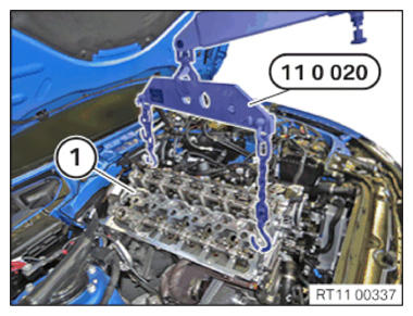
- With the help of a support person, use the workshop crane and special tool 0 490 567 (11 0 020) to insert, position and install cylinder head (1) and exhaust turbocharger.
- Ensure that the guide rails
of the timing chain are not
damaged.
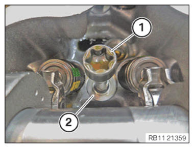
- Thread in and install the washers (2).
- Fit new cylinder head bolts (1).
Parts : Cylinder head bolts
- Do not wash away the coating of the cylinder head bolts (1).
- Lightly oil the contact surfaces of the screw heads of the cylinder head bolts.
- Make sure there is no coolant, water or motor oil in the threaded holes of the crankcase.
- Insert and install the cylinder head bolts (1).
NOTE:
TECHNICAL INFORMATION
When assembling, it is essential to observe screwing sequences and tightening torques.
Failure to comply with the regulations can lead to leaks and damage.
When assembling, it is essential to observe screwing sequences and tightening torques.
Failure to comply with the regulations can lead to leaks and damage.
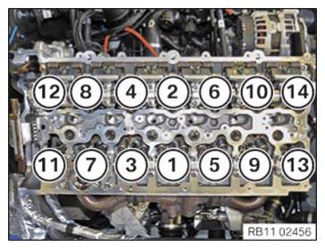
- Screw in the cylinder head bolts in sequence (1) to (14).
- Tighten cylinder head bolts with the special tool 0 495 747 (11 8 580) and 0 490 504 (00 9 120) in the order (1) to (14).
TIGHTENING TORQUES SPECIFICATION
| Cylinder head to crankcase | ||
| M11 Observe tightening sequence! Fit new cylinder head bolts. |
1. Joining torque | 30 Nm |
| 2. Angle of rotation | 90° | |
| 3. Angle of rotation | 180° | |
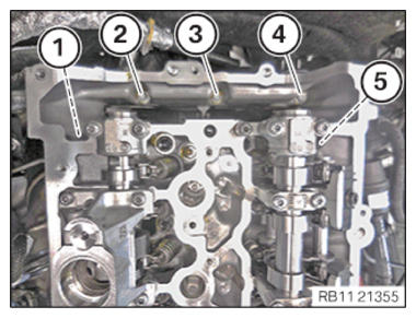
- Replace cylinder head bolts (1) by (5).
Parts : Cylinder head bolts
- Make sure no coolant, water or motor oil is in the threaded holes of the timing case cover.
- Screw in cylinder head bolts (1) to (5).
- Tighten the cylinder head bolts in the sequence (1) to (5).
TIGHTENING TORQUES SPECIFICATION
| Cylinder head bolt to timing case cover | ||
| M8x40 Replace screws. |
Tightening torque | 19 Nm |
- Feed in the camshaft sensor wheel (1) on the intake camshaft (2) and position.
- Rotate intake camshaft, if necessary in the position shown.
The recess (2) must point up.
- Tighten down screw (1).
TIGHTENING TORQUES SPECIFICATION
| Camshaft sensor wheel to intake camshaft | ||
| M4x35 | Tightening torque | 4.5 Nm |
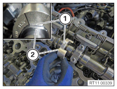
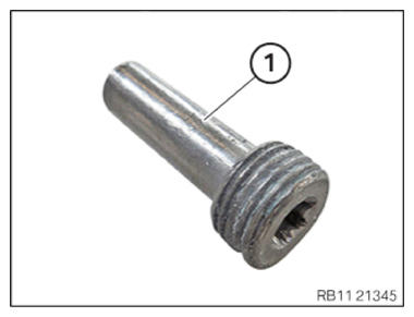
- Replace bearing journal (1).
Parts : Bearing journal
- Insert and install bearing journal (1) on the guide rail (2).
- Tighten the bearing journals (1).
TIGHTENING TORQUES SPECIFICATION
| Bearing journal to cylinder head | ||
| Bearing journal Replace the bearing journal! |
Tightening torque | 22 Nm |
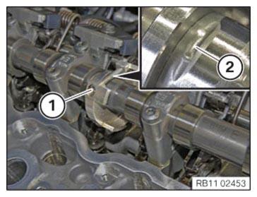
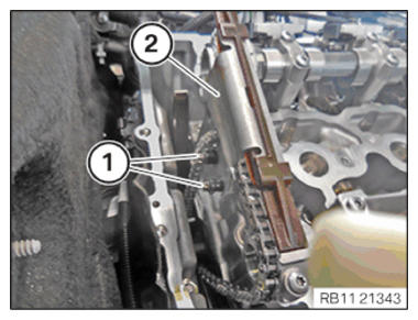
- Insert and install the slide rail (2).
- Tighten down screws (1).
TIGHTENING TORQUES SPECIFICATION
| Sliding rail to cylinder head | ||
| M6x16 | Tightening torque | 8 Nm |
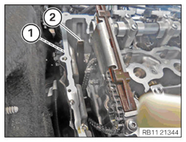
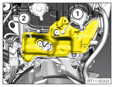
- Guide in and install cover (2).
- Tighten down screw (1).
TIGHTENING TORQUES SPECIFICATION
| Cover to rear cylinder head | ||
| M6 | Tightening torque | 8 Nm |
NOTE:
RISK OF DAMAGE
Improper routing of cables and wiring harnesses.
Trapped, crushed or damaged cables may cause short circuits and malfunctions.
Improper routing of cables and wiring harnesses.
Trapped, crushed or damaged cables may cause short circuits and malfunctions.
- Route all cables without abrasions, do not trap and crush.
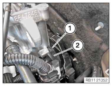
- Guide in and install the wiring harness section (2) for sensor system 1.
- Tighten down screw (1).
TIGHTENING TORQUES SPECIFICATION
| Cable bracket on rear cylinder head/transmission | ||
| M6 x 20 | Tightening torque | 8 Nm |
NOTE:
RISK OF DAMAGE
Improper routing of cables and wiring harnesses.
Trapped, crushed or damaged cables may cause short circuits and malfunctions.
Improper routing of cables and wiring harnesses.
Trapped, crushed or damaged cables may cause short circuits and malfunctions.
- Route all cables without abrasions, do not trap and crush.
- Feed in and install the transmission wiring harness (2) on the wiring harness section (3) for sensor system 1.
- Tighten down screws (1).
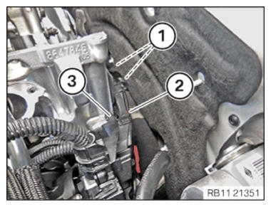
TIGHTENING TORQUES SPECIFICATION
| Cable bracket on rear cylinder head/transmission | ||
| M6 x 20 | Tightening torque | 8 Nm |
CAUTION:
Improper routing of the positive battery cable.
Risk of short circuits!
Risk of short circuits!
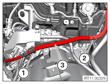
- Route the positive battery cable without abrasions and do not trap.
- Insert and install the positive battery cable (3).
- Secure clamps (1) and (2).
NOTE:
RISK OF DAMAGE
Improper routing of cables and wiring harnesses.
Trapped, crushed or damaged cables may cause short circuits and malfunctions.
Improper routing of cables and wiring harnesses.
Trapped, crushed or damaged cables may cause short circuits and malfunctions.
- Route all cables without abrasions, do not trap and crush.
- Connect connectors (2) and lock.
The connector must engage audibly.
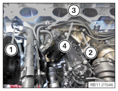
- Feed in and position the wiring harness section (4) of sensor system 1.
- Secure clamps (3).
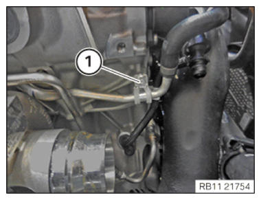
- Connect and lock coolant line (1).
- Make sure that the coolant line (1) engages audibly.
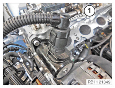
- Connect connectors (1) and lock.
The connector (1) must engage audibly.
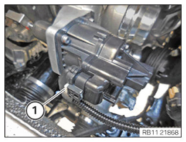
- Connect connectors (1) and lock.
The connector (1) must engage audibly.
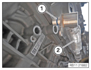
- Replace the sealing ring (1) on the coolant feed line (2) for the exhaust turbocharger with the special tool 0 496 714 (00 9 030)
.
Parts : Sealing ring
- Feed in and install the coolant feed line for the exhaust turbocharger (3).
- Tighten down screw (1).
TIGHTENING TORQUES SPECIFICATION
| Coolant feed line to crankcase | ||
| M6X12 | Tightening torque | 8 Nm |
- Tighten down screw (2).
TIGHTENING TORQUES SPECIFICATION
| Coolant feed line to crankcase | ||
| M6X12 | Tightening torque | 8 Nm |
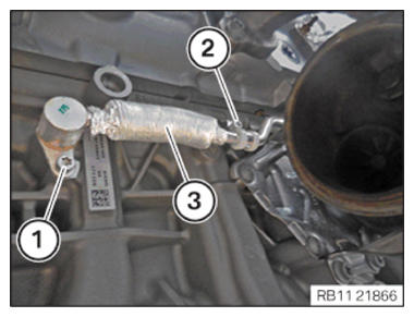
- Using the special tool 0 496 714 (00 9 030)
, replace the sealing ring (1) on the oil feed line (2) for the exhaust turbocharger.
Parts : Sealing ring
- Insert and install oil feed line (1) for the exhaust turbocharger.
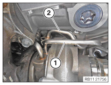
- Replace sealing ring on coolant return line (2) with special tool 0 496 714 (00 9 030)
.
Parts : Sealing ring
- Insert and install the coolant return line (2) for the exhaust turbocharger.
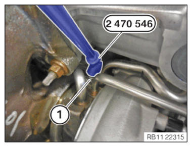
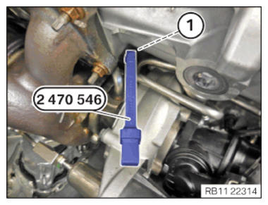
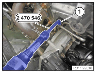
- Feed in screw (1) with special tool 2 470 546
and tighten hand-tight.
- Position special tool 2 470 546
on the screw (1).
- Tighten screw (1) with the special tool 2 470 546 .
TIGHTENING TORQUES SPECIFICATION
| Coolant return line/oil feed line to exhaust turbocharger | ||
| M6 x 12 | Tightening torque | 8 Nm |
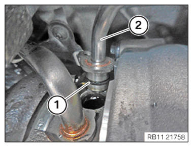
- Connect the coolant return line (1) for the exhaust turbocharger and lock.
- Make sure that the coolant return line (1) engages audibly.
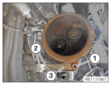
- Replace screw (1) and (2).
Parts : screw
- Feed in the support (3) and position it.
- Tighten down screws (2).
TIGHTENING TORQUES SPECIFICATION
| Exhaust turbocharger support to crankcase | ||
| M8 x 20 Replace screws. |
Tightening torque | 19 Nm |
- Tighten down screw (1).
TIGHTENING TORQUES SPECIFICATION
| Exhaust turbocharger to support | ||
| M8 x 25 Replace screw. |
Tightening torque | 19 Nm |
- Tighten down screw (1).
TIGHTENING TORQUES SPECIFICATION
| Coolant return line holder to crankcase | ||
| M6X12 | Tightening torque | 8 Nm |
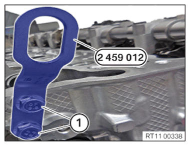
- Loosen the screws (1) from the special tool 2 459 012 .
- Guide out and remove the special tool 2 459 012 on the cylinder head.
Follow-up work
- Refer to ADJUSTING THE CAMSHAFTS WITH THE SPECIAL TOOL .
- Refer to INSTALLING THE INTAKE ADJUSTER .
- Refer to INSTALLING THE VANOS CENTRAL VALVE OF THE INTAKE ADJUSTER .
- Refer to INSTALL EXHAUST CAMSHAFT ADJUSTER .
- Refer to INSTALLING THE VANOS CENTRAL VALVE OF THE EXHAUST CAMSHAFT ADJUSTER .
- Refer to PRE-TENSIONING THE TIMING CHAIN WITH THE SPECIAL TOOL .
- Refer to TIGHTENING THE VANOS CENTRAL VALVE OF THE EXHAUST CAMSHAFT ADJUSTER .
- Refer to TIGHTENING THE VANOS CENTRAL VALVE OF THE INTAKE ADJUSTER .
- Refer to DISASSEMBLING ALL SPECIAL TOOLS
- Refer to INSTALL CHAIN TENSIONER .
- Refer to CHECKING THE TIMINGS OF THE CAMSHAFT .
- Refer to INSTALLING THE OIL RETURN LINE FOR THE EXHAUST TURBOCHARGER .
- Refer to INSTALL CATALYTIC CONVERTER .
- Refer to INSTALLING THE COOLANT LINE BETWEEN THE CYLINDER HEAD AND THE COOLANT PUMP .
- Refer to INSTALLING THE INTAKE PLENUM .
- Refer to INSTALLING THE TANK VENT VALVE .
- Refer to INSTALL CONTROL UNIT BRACKET .
- Refer to PARTIALLY INSTALLING THE INTEGRATED POWER SUPPLY MODULE (PDM) .
- Refer to INSTALLING THE DME CONTROL UNIT .
- Refer to INSTALLING CYLINDER HEAD COVER .
- Refer to INSTALLING BOTH ACTUATORS .
- Refer to PREPARE THE INJECTORS FOR INSTALLATION .
- Refer to INSTALLING THE HIGH-PRESSURE RAIL WITH INJECTORS OF THE CYLINDERS 4 TO 6 .
- Refer to INSTALLING RAIL WITH INJECTORS OF CYLINDERS 1 TO 3 .
- Refer to INSTALLING HIGH PRESSURE PUMP .
- Refer to INSTALLING FUEL DELIVERY LINE .
- Refer to INSTALLING THE HIGH-PRESSURE LINE BETWEEN THE HIGH-PRESSURE PUMP AND THE HIGH-PRESSURE RAIL .
- Refer to REPLACE SPARK PLUGS .
- Refer to INSTALL ALL IGNITION COILS .
- Refer to INSTALLING THE OXYGEN SENSOR MONITOR .
- Refer to INSTALLING LAMBDA OXYGEN SENSOR .
- Refer to INSTALL THE HOLDER OF THE POSITIVE BATTERY CABLE .
- Refer to INSTALLING ACOUSTIC COVER AT REAR .
- Refer to INSTALLING THE CENTER COWL UPPER PART .
- Refer to INSTALL TENSION STRUT ON SHOCK TOWER .
- Refer to INSTALLING WINDSHIELD PANEL COVER .
- Refer to INSTALL LEFT AND RIGHT WIPER ARM .
- Refer to INSTALL THE REAR RIGHT ENGINE COMPARTMENT COVER .
- Refer to INSTALL THE COVER OF THE ENGINE COMPARTMENT ON THE REAR LEFT .
- Refer to INSTALL THE FRONT HOOD SEAL AT THE REAR .
- Refer to INSTALL CHARGE AIR LINE .
- Refer to INSTALL BOTTOM CLEAN AIR PIPE .
- Refer to INSTALLING THE RESONATOR WITH THE TOP CLEAN AIR PIPE .
- Refer to INSTALLING THE INTAKE FILTER HOUSING (TENSION STRUT REMOVED ON SHOCK TOWER) .
- Refer to INSTALL FAN COWL .
- Refer to INSTALL THE REAR TOP CROSS CONNECTION .
- Refer to INSTALL FRONT CROSS CONNECTION .
- Refer to INSTALLING BOTH FRONT-END STRUTS
- Refer to INSTALLING THE COVER ON THE LEFT AND RIGHT IN THE ENGINE COMPARTMENT AT THE TOP
- Refer to INSTALLING THE COMPLETE EXHAUST SYSTEM .
- Refer to INSTALL THE CONNECTING SUPPORTS ON THE TUNNEL .
- Refer to IF INSTALLED: INSTALL THE TORSION STRUT ON THE RIGHT, AND ON THE LEFT WHERE REQUIRED .
- Refer to DISCONNECTING ALL BATTERY GROUND LEADS .
- Refer to ACTIVATING THE 48 V ELECTRICAL SYSTEM .
- Refer to FILL AND VENT THE HIGH-TEMPERATURE COOLANT CIRCUIT .
- Refer to FILL AND VENT THE LOW-TEMPERATURE COOLANT CIRCUIT .
- Refer to CHECK ENGINE OIL LEVEL .
- Refer to INSTALL THE COVER OF THE STEERING ASSEMBLY .
- Refer to INSTALL THE FRONT UNDERBODY PROTECTION OR FRONT THRUST FIELD .
- Refer to INSTALLING THE UNDERBODY PROTECTION OF THE STEERING GEAR OR THE FRONT THRUST FIELD .
- Refer to INSTALL THE CENTER UNDERBODY PROTECTION .
- Refer to INSTALL REAR UNDERBODY PROTECTION .
- Refer to INSTALLING ACOUSTIC COVER .
- Refer to TAKE HOOD OUT OF THE SERVICE POSITION .