Installing the left cylinder head
CAUTION:
Heavy component.
Heavy components can lead to injury or damage.
Heavy components can lead to injury or damage.
- Remove and install heavy components with the aid of another person/other persons.
CAUTION:
Swirling dirt particles caused by compressed air.
Injury hazard!
Injury hazard!
- Collect dirt particles, e.g. when blowing out, use cloth to do so.
- Wear safety goggles.
NOTE:
RISK OF DAMAGE
Damage to guide rails.
The application of great force can damage the guide rails of the timing chain.
Damage to guide rails.
The application of great force can damage the guide rails of the timing chain.
- When removing and installing the cylinder head, make sure that the cylinder head does not damage the guide rail.
NOTE:
RISK OF DAMAGE
Damage to the surface.
The use of metal-cutting tools (e.g., emery cloths) for cleaning surfaces can damage them and lead to leaks and/or engine damage.
Damage to the surface.
The use of metal-cutting tools (e.g., emery cloths) for cleaning surfaces can damage them and lead to leaks and/or engine damage.
- Do not use any metal-cutting tools.
NOTE:
TECHNICAL INFORMATION
When assembling, it is essential to observe screwing sequences and tightening torques.
When assembling, it is essential to observe screwing sequences and tightening torques.
Failure to comply with the regulations can lead to leaks and damage.
- Check if there are fluids or foreign materials present in the cylinder bores, remove fluids or foreign materials where required.
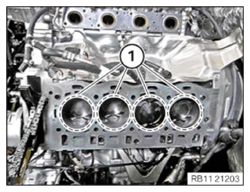
- Check the dowels (1) for correct seating and damage, replace if necessary.
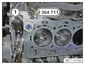
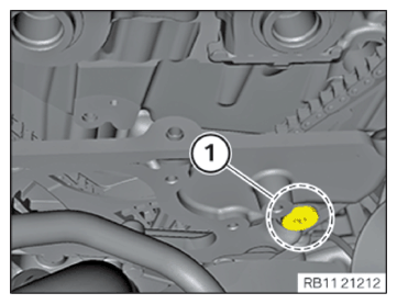
- Close the oil hole in the area (1) with a classification B plug from the set of special tools 2 364 711.
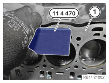
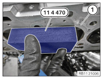
- Clean sealing surface (1) with special tool 0 495 103 (11 4 471) from the set of special tools 0 495 102 (11 4 470) .
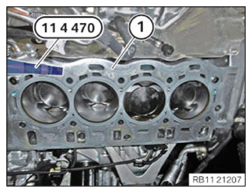
- Clean sealing surface (1) with special tool 0 495 104 (11 4 472) from the set of special tools 0 495 102 (11 4 470) .
NOTE:
TECHNICAL INFORMATION
If there are foreign bodies or fluids present in the bores, the tightening torque values can be falsified.
If there are foreign bodies or fluids present in the bores, the tightening torque values can be falsified.
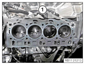
- Clean bores of cylinder head bolts (1) with compressed air.
- Clean sealing surface (1) with special tool 0 495 103 (11 4 471) from the set of special tools 0 495 102 (11 4 470) .
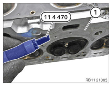
- Clean sealing surface (1) with special tool 0 495 104 (11 4 472) from the set of special tools 0 495 102 (11 4 470) .
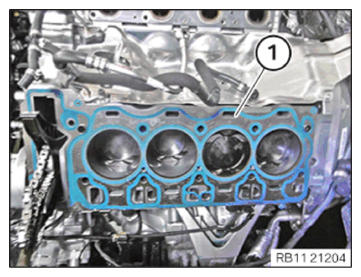
- Replace cylinder head gasket (1).
Parts: Cylinder head gasket
- Replace screws.
Parts: Screws
- Position cylinder head gasket (1) on the fitting sleeves on the engine block.
If the cylinder head has been reworked, a thicker cylinder head gasket must be installed.
NOTE:
TECHNICAL INFORMATION
The work must be performed with vehicle care to prevent component damage.
The work must be performed with vehicle care to prevent component damage.
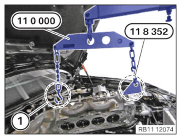
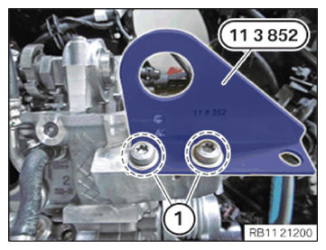
- Attach the special tool 0 490 561 (11 0 000) on the retaining tab (1) and on the special tool 0 494 116 (11 8 352) from the set of special tools 0 493 997 (11 8 350) .
- Position cylinder head with a workshop crane.
NOTE:
TECHNICAL INFORMATION
The work must be performed with vehicle care to prevent component damage.
The work must be performed with vehicle care to prevent component damage.
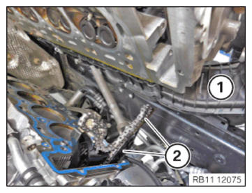
- Feed in and install the cylinder head with a workshop crane and 3 support persons carefully.
- When feeding in and installing the cylinder head (1), make sure that the slide rails and timing chain (2) are not damaged.
- Detach the special tool 0 490 567 (11 0 020) on the retaining tab (1) and on the special tool 0 494 116 (11 8 352) from the set of special tools 0 493 997 (11 8 350) .
Tightening left cylinder head
Tightening the left cylinder head
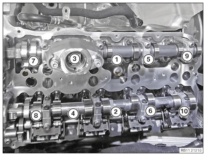
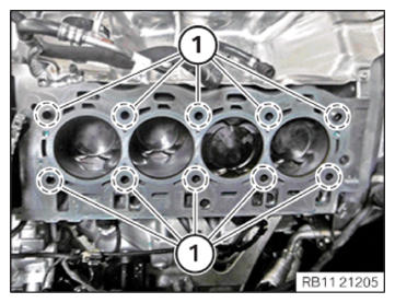
- Tighten screws in the order (1) to (10).
TIGHTENING TORQUES SPECIFICATION
| Cylinder head bolt | ||
| M11 Replace screws. |
Joining torque | 30 Nm |
| 1. Angle of rotation | 90° | |
| 2. Angle of rotation | 140° | |
- Release the screws (1) on the special tool 0 494 116 (11 8 352) from the set of special tools 0 493 997 (11 8 350) from the cylinder head.
- Remove the special tool 0 494 116 (11 8 352) from the set of special tools 0 493 997 (11 8 350) .
- Secure the screws (1) to the timing case cover.
TIGHTENING TORQUES SPECIFICATION
| Cylinder head bolt to timing case cover | ||
| M8x30 | Tightening torque | 23 Nm |
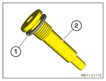
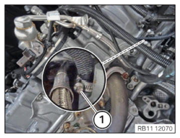
- Replace sealing ring (1).
Parts: Sealing ring
- Position sealing ring (1) on the bearing screw (2).
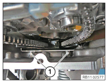
- Position the slide rail.
- Tighten the screw of the slide rail on the cylinder head of cylinder bank (1).
TIGHTENING TORQUES SPECIFICATION
| Slide rail to cylinder head | ||
| Bearing screw | Tightening torque | 25 Nm |
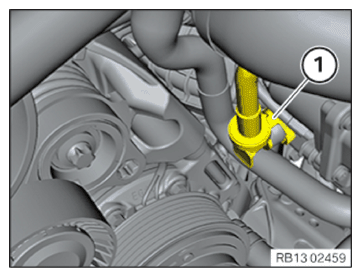
- Slide on the coolant hose.
- Tighten the hose clamp (1).
TIGHTENING TORQUES SPECIFICATION
| Coolant ventilation line | ||
| Hose clamp | Tightening torque | 1.5 Nm |
NOTE:
To provide a better overview: Schematic diagram with partially hidden components.
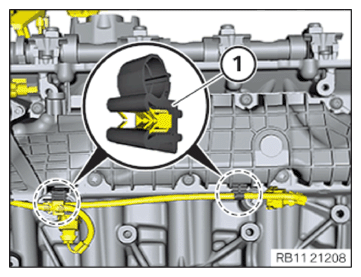
- Fix wiring harness mounting (1) below the intake system.
- Connect the quick-release coupling (1) and lock.
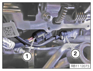
- Connect and lock the plug connection of the throttle valve (1).
- Connect the connector (1) to the servomotor and lock audibly.
- Connect the connector (2) to the pressure sensor on the intake plenum and lock audibly.
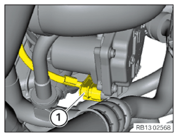
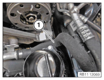
- Route the coolant line (1) between cylinder head and intake plenum.
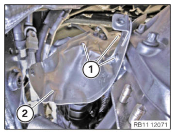
- Install the heat shield (2) on the rear of the cylinder head.
- Tighten down screws (1).
TIGHTENING TORQUES SPECIFICATION
| Heat protection plate | ||
| M6x16 | Tightening torque | 10 Nm |
Follow-up work
- Refer to INSTALLING BOTH LEFT VANOS ADJUSTERS .
- Refer to REMOVING SPECIAL TOOL TO PRETENSION TIMING CHAIN ON CYLINDER BANK 2 .
- Refer to INSTALLING THE HYDRAULIC CHAIN TENSIONER OF CYLINDER BANK 2 .
- Refer to INSTALLING THE SEALING CAP ON THE CYLINDER HEAD OF CYLINDER BANK 2 .
- Refer to INSTALLING THE LEFT CYLINDER HEAD COVER .
- Refer to INSTALLING VANOS SOLENOID ACTUATOR, INTAKE OF CYLINDER BANK 2 .
- Refer to INSTALL THE VANOS SOLENOID ACTUATOR EXHAUST OF CYLINDER BANK 2 .
- Refer to INSTALL THE LEFT HIGH PRESSURE PUMP .
- Refer to INSTALLING FUEL DELIVERY LINE .
- Refer to INSTALLING THE INJECTORS FOR THE CYLINDERS 5 TO 8 .
- Refer to INSTALL THE HIGH-PRESSURE RAIL ON THE LEFT .
- Refer to INSTALL THE IGNITION COILS OF CYLINDER BANK 2 .
- Refer to INSTALLING THE IGNITION COILS OF CYLINDERS 1 AND 5 .
- Refer to INSERT THE EXHAUST TURBOCHARGER FOR THE CYLINDERS 5 TO 8 .
- Refer to INSTALLING THE CLEAN AIR PIPE OF CYLINDER BANK 2 .
- Refer to INSTALLING CLEAN AIR PIPE OF CYLINDER BANK 1 .
- Refer to INSTALLING BOTH CHARGE AIR COOLERS .
- Refer to CONNECTING THE RIGHT CHARGE AIR LINE TO THE EXHAUST TURBOCHARGER .
- Refer to CONNECTING THE LEFT CHARGE AIR LINE TO THE EXHAUST TURBOCHARGER .
- Refer to CLOSING THE HIGH-TEMPERATURE COOLANT CIRCUIT .
- Refer to INSTALL THE COOLANT EXPANSION TANK FOR THE LOW-TEMPERATURE COOLANT CIRCUIT (CHARGE AIR COOLER) .
- Refer to SEALING OFF COOLANT FOR LOW-TEMPERATURE COOLANT CIRCUIT .
- Refer to INSTALLING THE UNDERBODY PROTECTION OF THE STEERING GEAR OR THE FRONT THRUST FIELD .
- Refer to INSTALL THE FRONT UNDERBODY PROTECTION OR FRONT THRUST FIELD .
- Refer to INSTALLING THE FRONT LEFT BOTTOM WHEEL ARCH COVER .
- Refer to INSTALLING THE FRONT BOTTOM RIGHT WHEEL ARCH COVER .
- Refer to INSTALL DRIVE BELT .
- Refer to INSTALLING FAN COWL .
- Refer to INSTALL THE REAR TOP CROSS CONNECTION .
- Refer to INSTALL FRONT CROSS CONNECTION .
- Refer to INSTALLING THE RIGHT INTAKE FILTER HOUSING WITH THE RIGHT FRONT-END STRUT .
- Refer to INSTALLING LEFT INTAKE FILTER HOUSING WITH LEFT FRONT-END STRUT .
- Refer to INSTALLING THE COVER ON THE LEFT AND RIGHT IN THE ENGINE COMPARTMENT AT THE TOP
- Refer to INSTALLING THE CATALYTIC CONVERTER FOR CYLINDERS 5 TO 8 .
- Refer to RELEASING THE HEAT SHIELD .
- Refer to INSTALLING THE CENTER COWL UPPER PART .
- Refer to INSTALL TENSION STRUT ON SHOCK TOWER .
- Refer to INSTALLING WINDSHIELD PANEL COVER .
- Refer to INSTALL LEFT AND RIGHT WIPER ARM .
- Refer to INSTALL THE REAR RIGHT ENGINE COMPARTMENT COVER .
- Refer to INSTALL THE COVER OF THE ENGINE COMPARTMENT ON THE REAR LEFT .
- Refer to INSTALL RIGHT HEAT SHIELD .
- Refer to INSTALL LEFT HEAT SHIELD .
- Refer to INSTALL HEAT SHIELD, TOP .
- Refer to INSTALLING THE RIGHT OXYGEN SENSOR MONITOR .
- Refer to INSTALLING THE LEFT OXYGEN SENSOR MONITOR .
- Refer to PARTLY INSTALLING THE RIGHT LAMBDA OXYGEN SENSOR .
- Refer to PARTIALLY INSTALLING THE LEFT LAMBDA OXYGEN SENSOR .
- Refer to INSTALLING THE RETAINING BRIDGE IN VEHICLES WITH A GASOLINE PARTICULATE FILTER .
- Refer to INSTALLING THE RETAINING BRIDGE .
- Refer to INSTALL EXHAUST SYSTEM .
- Refer to INSTALLING CENTER REAR UNDERSHIELD .
- Refer to INSTALL THE CONNECTING SUPPORTS ON THE TUNNEL .
- Refer to INSTALLING THE CONTROL UNIT BRACKET FOR CYLINDERS 5 TO 8 .
- Refer to INSTALLING THE COVER OF THE LEFT DME CONTROL UNIT .
- Refer to INSTALLING CONTROL UNIT HOLDER FOR CYLINDERS 1 TO 4 .
- Refer to INSTALLING THE COVER OF THE RIGHT DME CONTROL UNIT .
- Refer to DISCONNECTING ALL BATTERY GROUND LEADS .
- Refer to FILL AND VENT THE LOW-TEMPERATURE COOLANT CIRCUIT .
- Refer to FILL AND VENT THE HIGH-TEMPERATURE COOLANT CIRCUIT .
- Refer to EVACUATE AND CHARGE CONDITIONING .